2007 Buell Ulysses: Chassis
2-57
HOME
6.
See
Figure 2-82.
Hold the forcing screw while tightening
the nut to draw the bearing into the steering head. Con-
tinue tightening until the bearing is fully seated.
7.
Visually check to make sure the bearing is completely
seated against the shoulder in the steering head.
8.
Repeat this process for the lower bearing.
9.
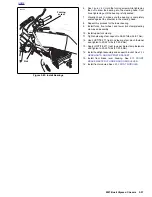
Install forks, front wheel, and lower fork clamp/steering
stem as an assembly.
10. Install upper fork clamp.
11. Tighten steering stem capnut to 38-42 ft-lbs (52-57 Nm).
12. Use LOCTITE 271 (red) on steering stem pinch fastener
and tighten to 20-22 ft-lbs (27-29.8 Nm).
13. Apply LOCTITE 271 (red) to upper triple clamp fasteners
and tighten to 23-25 ft-lbs (31-33.8 Nm).
14. Install headlight assembly and support bracket. See
2.28
HEADLIGHTS AND SUPPORT BRACKET
.
15. Install front brake lever housing. See
2.10 FRONT
BRAKE MASTER CYLINDER AND HAND LEVER
.
16. Install front modules. See
2.29 FRONT MODULES
.
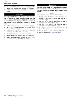
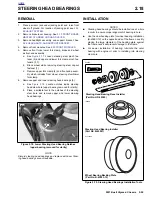
Figure 2-82. Install Bearings
i04255
Forcing
screw
Nut
Summary of Contents for 2007 ULYSSES
Page 17: ...A 16 2007 Buell Ulysses Appendix A HOME NOTES ...
Page 51: ...D 2 2007 Buell Ulysses Appendix D HOME Figure D 2 Rear Brake Systems Top View b1115acsxu ...
Page 63: ...D 14 2007 Buell Ulysses Appendix D HOME NOTES ...
Page 73: ......
Page 103: ...1 30 2007 Buell Ulysses Maintenance HOME NOTES ...
Page 129: ......
Page 237: ...2 108 2007 Buell Ulysses Chassis HOME NOTES ...
Page 239: ......
Page 309: ...3 70 2007 Buell Ulysses Engine HOME NOTES ...
Page 347: ...3 108 2007 Buell Ulysses Engine HOME NOTES ...
Page 391: ...4 42 2007 Buell Ulysses Fuel System HOME NOTES ...
Page 481: ......
Page 505: ......
Page 561: ...6 56 2007 Buell Ulysses Drive Transmission HOME NOTES ...
Page 563: ......
Page 587: ...7 24 2007 Buell Ulysses Electrical HOME NOTES ...
Page 645: ...7 82 2007 Buell Ulysses Electrical HOME NOTES ...
Page 647: ......


