2-62
2007 Buell Ulysses: Chassis
HOME
FRONT AND REAR ISOLATORS
2.20
FRONT ISOLATOR
Removal
NOTE
Avoid cross-threading front isolator bolt or insert. Keep weight
of motorcycle off front isolator by alternately loosening front
isolator bolt and raising scissor jack to support engine.
1.
Place a scissor jack under jacking point for supporting
engine only. For location of jacking point see
2.32
EXHAUST SYSTEM.
2.
See
Figure 2-87.
Remove clutch cable wire form.
3.
See
Figure 2-88.
Remove front isolator bolt (6).
4.
Remove front isolator mount fasteners (5).
5.
Remove front isolator bracket (4).
6.
Remove upper snubber fastener (2) and remove upper
snubber (1).
Installation
1.
See
Figure 2-88.
If the threaded insert (3) is damaged
and needs to be replaced, install new insert with LOC-
TITE 271 (red) and tighten to 59-61 ft-lbs (80-82.7 Nm).
2.
Loosely install front isolator bracket (4) with front isolator
bolt (6).
3.
See
Figure 2-88.
Install front isolator bracket fasteners
(5), and tighten to 49-51 ft-lbs (66-69 Nm).
CAUTION
Avoid cross-threading front isolator bolt or insert. Keep
weight of motorcycle off front isolator by alternately
tightening front isolator bolt and raising scissor jack to
support engine.
4.
Tighten front isolator bolt (6) to 49-51 ft-lbs (66-69 Nm).
NOTE
Hold wire form while tightening to prevent it from twisting.
5.
See
Figure 2-87.
Install clutch cable wire form. Tighten
fastener to 84-92 in-lbs (9.5-10.4 Nm).
NOTE
See
Figure 2-88.
If the threaded insert (3) is damaged and
needs to be replaced, install new insert with LOCTITE 271
(red) and tighten to 59-61 ft-lbs (80-82.7 Nm).
REAR ISOLATOR
NOTE
It is necessary to remove engine to access rear isolator.
See
3.4 STRIPPING MOTORCYCLE FOR ENGINE SER-
VICE
to access the rear isolator.
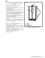
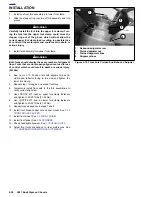
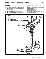
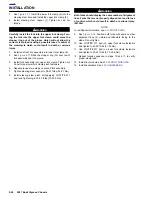
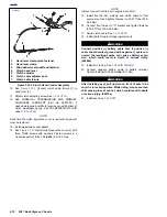
Figure 2-87. Clutch Cable Wire Form
10500
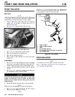
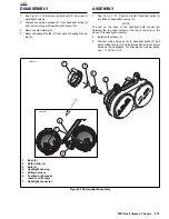
Figure 2-88. Front Isolator
b1040x2x
1.
Upper snubber
2.
Upper snubber fastener
3.
Insert
4.
Front isolator bracket
5.
Front isolator bracket fastener to engine (2)
6.
Front isolator bolt
1
2
3
4
6
5
Summary of Contents for 2007 ULYSSES
Page 17: ...A 16 2007 Buell Ulysses Appendix A HOME NOTES ...
Page 51: ...D 2 2007 Buell Ulysses Appendix D HOME Figure D 2 Rear Brake Systems Top View b1115acsxu ...
Page 63: ...D 14 2007 Buell Ulysses Appendix D HOME NOTES ...
Page 73: ......
Page 103: ...1 30 2007 Buell Ulysses Maintenance HOME NOTES ...
Page 129: ......
Page 237: ...2 108 2007 Buell Ulysses Chassis HOME NOTES ...
Page 239: ......
Page 309: ...3 70 2007 Buell Ulysses Engine HOME NOTES ...
Page 347: ...3 108 2007 Buell Ulysses Engine HOME NOTES ...
Page 391: ...4 42 2007 Buell Ulysses Fuel System HOME NOTES ...
Page 481: ......
Page 505: ......
Page 561: ...6 56 2007 Buell Ulysses Drive Transmission HOME NOTES ...
Page 563: ......
Page 587: ...7 24 2007 Buell Ulysses Electrical HOME NOTES ...
Page 645: ...7 82 2007 Buell Ulysses Electrical HOME NOTES ...
Page 647: ......


