B-12
2007 Buell Ulysses: Appendix B
HOME
PUSH-TO-SEAT TERMINALS
The Packard push-to-seat terminal connectors found on Soft-
ail model vehicles are listed below.
●
Ignition Switch [33]
●
Fuse Terminals
●
MAP Sensor [80]
Removing Push-to-Seat Terminals
Like most connectors, Packard push-to-seat terminals are
pulled out the wire end of the connector. To remove a push-
to-seat terminal, proceed as follows:
1.
Remove the connector from the retaining device, if
present.
2.
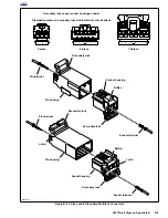
Bend back the external latch(es) slightly and separate
the pin and socket halves of the connector.
NOTE
Both the Ignition Light/Key Switch and the Main Power con-
nectors are provided with secondary locks. The secondary
lock, which may be molded onto the connector or exist as a
separate piece, aids in terminal retention. Secondary locks
must be opened (or removed) before the terminals can be
extracted from the connector housing.
3.
Open or remove the secondary lock. Bend back the latch
slightly and free one side of the secondary lock, then
repeat the step to release the other side. Rotate the sec-
ondary lock outward on hinge to access the terminals in
the chambers of the connector housing.
4.
Looking in the mating end or terminal side of the connec-
tor (opposite the secondary lock), take note of the larger
cavity next to each terminal.
5.
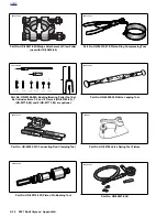
Insert the pick (Snap-On TT600-3) into the cavity until it
stops. Pivot the end of the pick toward the terminal to
depress the locking tang. Remove the pick and gently
tug on the wire to pull the terminal from the wire end of
the connector. Repeat the step if the terminal is still
locked in place.
NOTE
A series of Packard Electrical Terminal Crimp Tools are avail-
able to install Packard pin and socket terminals on wires. If
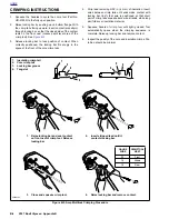
new terminals must be installed, see Crimping Instructions.
Installing Push-to-Seat Terminals
NOTE
For wire location purposes, alpha characters are stamped
onto the secondary locks or onto the wire end of the connec-
tor housing.
1.
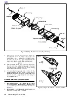
To install a terminal back into the chamber of the connec-
tor housing, use a thin flat blade, like that on an X-Acto
knife, and carefully bend the tang outward away from the
terminal body.
2.
Push the lead into the chamber at the wire end of the
connector. A click is heard when the terminal is properly
seated.
3.
Gently tug on the wire end to verify that the terminal is
locked in place and will not back out of the chamber.
4.
Close or install the secondary lock. Rotate the hinged
secondary lock inward until tabs fully engage latches on
both sides of connector.
5.
Push the pin and socket halves of the connector together
until the latches “click.”
6.
Install connector on retaining device, if present.
Summary of Contents for 2007 ULYSSES
Page 17: ...A 16 2007 Buell Ulysses Appendix A HOME NOTES ...
Page 51: ...D 2 2007 Buell Ulysses Appendix D HOME Figure D 2 Rear Brake Systems Top View b1115acsxu ...
Page 63: ...D 14 2007 Buell Ulysses Appendix D HOME NOTES ...
Page 73: ......
Page 103: ...1 30 2007 Buell Ulysses Maintenance HOME NOTES ...
Page 129: ......
Page 237: ...2 108 2007 Buell Ulysses Chassis HOME NOTES ...
Page 239: ......
Page 309: ...3 70 2007 Buell Ulysses Engine HOME NOTES ...
Page 347: ...3 108 2007 Buell Ulysses Engine HOME NOTES ...
Page 391: ...4 42 2007 Buell Ulysses Fuel System HOME NOTES ...
Page 481: ......
Page 505: ......
Page 561: ...6 56 2007 Buell Ulysses Drive Transmission HOME NOTES ...
Page 563: ......
Page 587: ...7 24 2007 Buell Ulysses Electrical HOME NOTES ...
Page 645: ...7 82 2007 Buell Ulysses Electrical HOME NOTES ...
Page 647: ......

