3-56
2007 Buell Ulysses: Engine
HOME
7.
See
Figure 3-77.
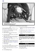
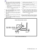
Coat the sleeve with oil and place a
new seal and lower collar assembly over the valve stem
and onto valve guide.
NOTES
●
See
Figure 3-76.
The valve seal is now incorporated into
the lower collar and is installed by hand. NO SPECIAL
TOOLS ARE REQUIRED.
●
The seal is completely installed when the lower collar
contacts the machined surface of the head.
●
Do not remove valve after seal is installed. Repeated
installations will damage seal.
8.
Install valve spring and upper collar.
9.
See
Figure 3-78.
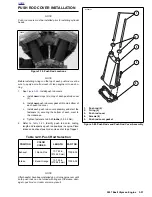
Compress spring with
VALVE SPRING
COMPRESSOR (Part No. HD-34736B).
NOTE
A single valve spring is used for each valve. The inner and
outer springs are combined into one tapered spring that is
progressively wound.
10. Insert valve keepers into upper collar, making sure they
engage grooves in valve stem.
11. Release and remove from VALVE SPRING COMPRES-
SOR.
12. Repeat Steps 4-11 for the remaining valve.
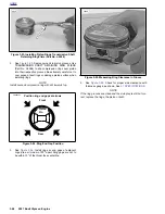
Figure 3-77. Valve Seal and Lower Collar Assembly
Installation
8705
Figure 3-78. Valve Spring Compressor
(Part No. HD-34736B)
8684
Summary of Contents for 2007 ULYSSES
Page 17: ...A 16 2007 Buell Ulysses Appendix A HOME NOTES ...
Page 51: ...D 2 2007 Buell Ulysses Appendix D HOME Figure D 2 Rear Brake Systems Top View b1115acsxu ...
Page 63: ...D 14 2007 Buell Ulysses Appendix D HOME NOTES ...
Page 73: ......
Page 103: ...1 30 2007 Buell Ulysses Maintenance HOME NOTES ...
Page 129: ......
Page 237: ...2 108 2007 Buell Ulysses Chassis HOME NOTES ...
Page 239: ......
Page 309: ...3 70 2007 Buell Ulysses Engine HOME NOTES ...
Page 347: ...3 108 2007 Buell Ulysses Engine HOME NOTES ...
Page 391: ...4 42 2007 Buell Ulysses Fuel System HOME NOTES ...
Page 481: ......
Page 505: ......
Page 561: ...6 56 2007 Buell Ulysses Drive Transmission HOME NOTES ...
Page 563: ......
Page 587: ...7 24 2007 Buell Ulysses Electrical HOME NOTES ...
Page 645: ...7 82 2007 Buell Ulysses Electrical HOME NOTES ...
Page 647: ......

