2007 Buell Ulysses: Drive/Transmission
6-45
HOME
TRANSMISSION RIGHT CASE BEARINGS
6.12
GENERAL
REMOVAL
1.
Split crankcases. See
6.8 CASE DISASSEMBLY FOR
TRANSMISSION REMOVAL.
Countershaft Needle Bearing
1.
See
Figure 6-84.
From inside transmission case use a
suitable BEARING DRIVER/PULLER
to remove counter-
shaft bearing (8) from crankcase bore.
Shifter Drum Bushing
1.
The shifter drum bushing (12) is a press fit in the right
crankcase half. Inspect the bushing against the corre-
sponding end of the shifter drum for proper fit and wear.
2.
If bushing is to be replaced, use BUSHING AND BEAR-
ING PULLER (Part No. HD-95760-69A) with 1/2 IN.
COLLET (Part No. HD-95765-69A) to remove bushing
from crankcase bore.
INSTALLATION
Countershaft Needle Bearing
1.
Find a suitable bearing driver 1-1/4 in. (31.75 mm) in
diameter.
2.
See
Figure 6-84.
From the outside of the case place the
closed end needle bearing (11) open end first next to the
bearing bore. Hold the driver squarely against the closed
end of the bearing and tap the bearing into place. The
bearing is properly positioned when it is driven flush or
0.030 in. (0.762 mm) below the outside surface of the
case.
3.
Lubricate bearing with GENUINE HARLEY-DAVIDSON
TRANSMISSION AND PRIMARY CHAIN-
CASE LUBRICANT (Part No. 99851-05).
Shifter Drum Bushing
1.
See
Figure 6-84.
Using SNAP-ON BUSHING DRIVER
SET (Part No. A-157C) with a 1/2 inch adapter (Part No.
A157-8), install new bushing (12).
2.
Lubricate bushing with GENUINE HARLEY-DAVIDSON
TRANSMISSION AND PRIMARY CHAIN-
CASE LUBRICANT (Part No. 99851-05).
PART NO.
SPECIALTY TOOL
HD-95760-69A
Bushing and bearing puller
HD-95765-69A
1/2 in. collet
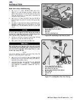
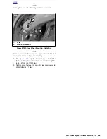
Figure 6-84. Transmission Assembly-Right Crankcase Half
1.
Retaining ring
2.
Bearing (Inner)
3.
Fifth gear mainshaft
4.
Bearing (Outer)
5.
O-ring
6.
Oil seal
7.
Right crankcase half
8.
Ball bearing with spacer
9.
Retaining ring
10. Oil seal
11. Bearing, (closed end) countershaft
12. Bushing, shifter drum
b1013b6x
10
8
5
3
2
12
4
6
7
9
11
1
Summary of Contents for 2007 ULYSSES
Page 17: ...A 16 2007 Buell Ulysses Appendix A HOME NOTES ...
Page 51: ...D 2 2007 Buell Ulysses Appendix D HOME Figure D 2 Rear Brake Systems Top View b1115acsxu ...
Page 63: ...D 14 2007 Buell Ulysses Appendix D HOME NOTES ...
Page 73: ......
Page 103: ...1 30 2007 Buell Ulysses Maintenance HOME NOTES ...
Page 129: ......
Page 237: ...2 108 2007 Buell Ulysses Chassis HOME NOTES ...
Page 239: ......
Page 309: ...3 70 2007 Buell Ulysses Engine HOME NOTES ...
Page 347: ...3 108 2007 Buell Ulysses Engine HOME NOTES ...
Page 391: ...4 42 2007 Buell Ulysses Fuel System HOME NOTES ...
Page 481: ......
Page 505: ......
Page 561: ...6 56 2007 Buell Ulysses Drive Transmission HOME NOTES ...
Page 563: ......
Page 587: ...7 24 2007 Buell Ulysses Electrical HOME NOTES ...
Page 645: ...7 82 2007 Buell Ulysses Electrical HOME NOTES ...
Page 647: ......

