2003 Buell XB9R: Chassis
2-45
HOME
FORK CLAMPS, UPPER AND LOWER
2.17
REMOVAL
1.
Remove front fork assemblies. See
2.16 FRONT FORK
.
2.
Remove handlebars. See
2.27 HANDLEBARS
.
3.
See
Figure 2-68.
Remove cable straps attached to the
upper fork clamp.
4.
Remove intake cover. assembly. See
2.34 INTAKE
COVER ASSEMBLY
.
5.
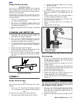
See
Figure 2-69.
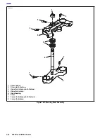
Remove steering stem pinch fastener
(2).
6.
Under right side of front fairing, cut cable strap holding
ignition switch, fuse block and right handlebar switch
wires. See
7.3 IGNITION/HEADLIGHT KEY SWITCH
.
7.
Unplug the ignition switch. See
7.3 IGNITION/HEAD-
LIGHT KEY SWITCH
.
8.
See
Figure 2-69.
Hold or brace the lower fork clamp and
remove steering stem cap (1).
9.
Remove the upper fork clamp (4).
10. Remove the lower fork clamp (8).
11. Remove ignition switch. See
7.3 IGNITION/HEADLIGHT
KEY SWITCH
.
12. If steering head bearings need replacing, see
2.18
STEERING HEAD BEARINGS
.
INSTALLATION
1.
See
Figure 2-69.
Install the lower fork clamp (8) into the
steering stem bore and install the upper fork clamp (4).
2.
Install steering stem cap (1). Tighten but do not torque.
1
1
WARNING
1
WARNING
Carefully install the fork into the upper fork clamp. Forc-
ing the fork into the upper fork clamp could move the
stopper ring out of the groove which will not allow the
correct clamp load causing a possible loss of control of
the motorcycle which could result in death or serious
injury.
3.
Install one front fork assembly into lower fork clamp (8).
4.
See
Figure 2-67.
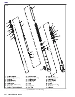
Slide the stopper ring (19) over top of
fork assembly and into groove.
5.
Install upper clamp on fork assembly. Tighten but do not
torque lower fork clamp pinch fasteners.
6.
Repeat previous two steps on second fork assembly.
7.
Tighten steering stem cap to 38-42 ft-lbs (52-57 Nm).
8.
Install steering stem pinch bolt applying LOCTITE 272
and tightening to 17-19 ft-lbs (23-26 Nm).
1
1
WARNING
1
WARNING
Both forks should display the same number of alignment
lines. Forks that are not properly aligned may lead to a
loss of control which could result in death or serious
injury.
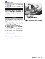
9.
See
Figure 2-66.
Position both forks with same number
alignment lines (4) visible and reflectors facing to the
sides. Do not tighten.
10. Use LOCTITE 272 on upper fork clamp fasteners and
tighten to 17-19 ft-lbs (23-26 Nm).
11. Use LOCTITE 272 on lower fork clamp fasteners and
tighten to 13-15 ft-lbs (18-20 Nm).
12. Repeat torque sequence in steps 10 and 11.
13. Install intake cover assembly. See
2.34 INTAKE COVER
ASSEMBLY
.
14. Install handlebars. See
2.27 HANDLEBARS
.
15. See
Figure 2-68.
Install cable straps.
a. Install cable strap to the right of ignition switch
securing right hand switch and brake line wires to
upper fork clamp.
b.
Install cable strap to the left of ignition switch secur-
ing left hand switch and clutch cable wires to upper
fork clamp.
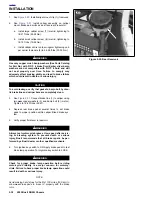
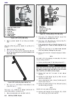
Figure 2-68. Cable Straps On Upper Fork Clamp
8454
Summary of Contents for XB9R 2003
Page 2: ...1 2 Edit Me Printed June 5 2002 12 26 pm ...
Page 35: ...D 2 2003 Buell XB9R Appendix D HOME Figure D 2 Rear Brake Systems Top View b1115xbx ...
Page 36: ...2003 Buell XB9R Appendix D D 3 HOME Figure D 3 Rear Brake Systems Left Side View b1116xcx ...
Page 47: ...D 14 2003 Buell XB9R Appendix D HOME NOTES ...
Page 49: ......
Page 77: ...1 28 2003 Buell XB9R Maintenance HOME NOTES ...
Page 103: ...1 54 2003 Buell XB9R Maintenance HOME NOTES ...
Page 105: ... 2 ...
Page 191: ......
Page 263: ...3 72 2003 Buell XB9R Engine HOME NOTES ...
Page 299: ...4 2 2003 Buell XB9R Fuel System HOME NOTES ...
Page 385: ...4 88 2003 Buell XB9R Fuel System HOME NOTES ...
Page 421: ...4 124 2003 Buell XB9R Fuel System HOME NOTES ...
Page 423: ......
Page 445: ...5 22 2003 Buell XB9R Starter HOME NOTES ...
Page 447: ......
Page 469: ...6 22 2003 Buell XB9R Drive Transmission HOME NOTES ...
Page 497: ...6 50 2003 Buell XB9R Drive Transmission HOME NOTES ...
Page 499: ......


