background image

CC 

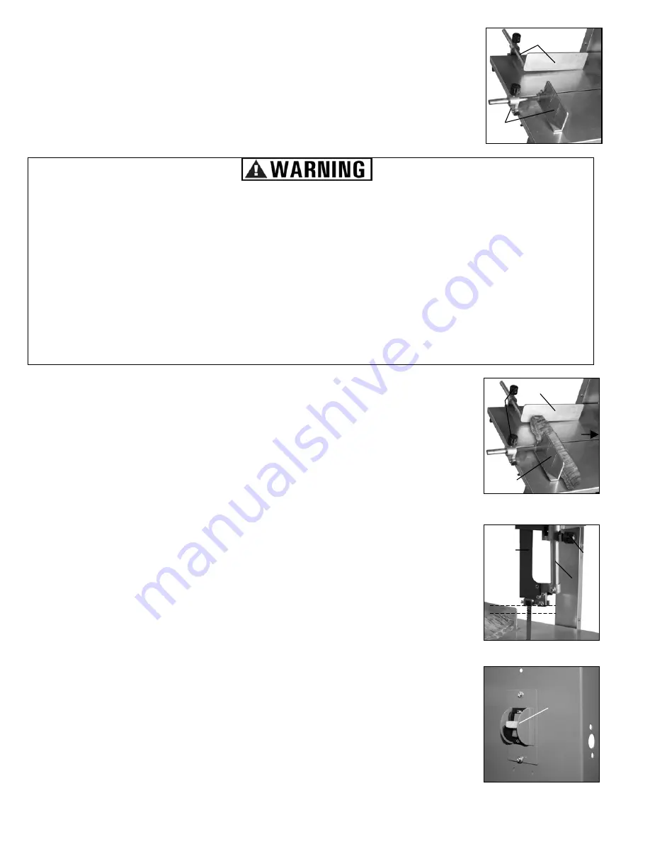
DD 

Assembling the Fence and Pusher


The fence (CC) and pusher (DD) have predetermined spaces for attachment to the 
table. The fence attaches to the side, the pusher attaches to the end. Using socket 
screws, attach the fence and pusher to their respective areas. (Figure 16) 

 
OPERATION 

MBSAW Meat Cutting Band Saw w/Meat Grinder  Assembly & Operating Instructions 

10


NOTE: For best results, chilled or slightly frozen meats make uniform cutting easier. 
However, do not cut completely frozen meat as it may damage the blade.


Basic Meat Cutting Procedures


Place the meat on the stainless steel table and position it between the saw blade 
in front (EE, out of picture), the pusher (FF), and the fence (GG) on the left. Note: 
The fence and the pusher have adjusting knobs (HH) allowing you to adjust the 
placement of both, depending on the size of the piece of meat. (Figure 17)


Adjust the vertical placement of the Blade Guard (II) so there is a maximum 1/2" 
space between it and the top of the meat to be cut. To adjust the Blade Guard, 
loosen the knob (JJ) on the Blade Guard and raise or lower it to expose more or 
less of the blade. Once in the desired position, tighten the knob. NOTE: There is 
a flat side on the Guide Post (KK) that must face the knob to work properly. 
(Figure 18)


Turn the Power On using the ON/OFF switch (LL). Allow the blade to reach full 
speed. With one hand on the pusher and the other on the fence, push the table 
forward into the rotating blade, careful to keep your hands out of the path of the 
blade. (Figure 19) 
 
Cover the machine with a cloth cover when not in use. 


Before and after use, wash all parts with warm soapy water. 

Wear protective gloves, clothing and eye protection while operating the Band Saw. 

Saw blade and grinder knife are sharp! 

Use care when using and cleaning the product to prevent injury. 

Dull blades require extra effort, which leads to blade breakage, resulting in flying debris and possible injury 

to the user or bystanders. 

Once the cut is made, turn the machine off and allow the blade to come to a complete stop before 

removing the cut meat. Repeat this process until finished with the original piece of meat. 

Proper blade tension is important, both for optimum cutting and safety. There should be no 

flexibility with the blade.


Figure 16


HH 

GG 

FF 

Figure 17


EE 

II  

JJ 

1/2"

Figure 18               

KK 

LL

Figure 19


Summary of Contents for IW12BX

Page 1: ...t to change this product at any time without prior notice IF THERE IS ANY QUESTION ABOUT A CONDITION BEING SAFE OR UNSAFE DO NOT OPERATE THIS PRODUCT HAVE QUESTIONS OR PROBLEMS DO NOT RETURN THIS PRODUCT TO THE RETAILER CONTACT BUFFALO TOOLS If you experience a problem or need parts for this product visit our website http www buffalotools com or call our customer help line at 1 888 287 6981 Monday...

Page 2: ...n which if not avoided could result in death or serious injury READ AND UNDERSTAND ALL INSTRUCTIONS Failure to follow all instructions may result in electric shock fire and or serious personal injury WHAT YOU NEED TO KNOW ABOUT SAFETY INSTRUCTIONS The warning and safety instructions appearing in this manual are not meant to cover all possible conditions and situations that may occur Common sense c...

Page 3: ...ng Band Saw w Meat Grinder Assembly Operating Instructions 3 1 Cover 2 Blade Guard 3 Fence 4 Pusher 5 Pusher Locking Knob 6 Sliding Stainless Steel Table 7 Front Access Door 8 Front Motor Access Panel 9 Rubber Feet 10 Steel Stand 11 Meat Grinder Assembly Locking Handle 12 Tube Connector 13 Meat Grinder Intake 14 Stuffer Tool 15 Blade Guard Adjustment Knob Rated Current 6 Amps Maximum Cutting Depth...

Page 4: ...long hair Wear rubber footwear Always wear safety goggles and ear protection when using the product Prevent electrical shock Keep the power cord away from heat oil sharp edges and rough surfaces Do not operate if power cord is frayed or damaged Never move the product while it is plugged into an electrical outlet Make sure the switch is in the OFF position when the power cord is plugged in Never us...

Page 5: ... parts operate smoothly and efficiently Make sure that all moving parts are in good working order Check the machine for any broken parts Make sure all parts are fitted properly and any other conditions that might affect the proper functioning of the machine are correct Do not use the machine when it cannot be switched on or off For your own safety use only accessories recommended in this manual Se...

Page 6: ...r will not line up properly with the Drive Wheel in the upper housing Ignore the holes on top of Part 95 as they serve no purpose Once the stand and motor are assembled attach it to the main body of the saw using three long bolts through the three elliptical openings A in the Upper Cover Part 78 A Back Front Bottom Top Figure 1 Figure 2 A B C Once the base is assembled attach the Drive Belt Part 5...

Page 7: ...ve Wheel and saw blade Then remove the Blade Guard F and Upper Guard Plate G Figure 5 NOTE For best results stand to the left front of the table while performing the following steps Turning the nut H counterclockwise lowers and decreases tension on the Drive Wheel I allowing you to adjust the alignment of the blade or to replace the blade entirely Figure 6 H J I K Figure 6 To center the blade on t...

Page 8: ... the Blade Guide will move it toward or away from the blade Finally loosen the socket screw U to move the Bearing V toward or away from the blade For best results the bearing should be 1 32 away from the blade Figure 11 N Once these steps are complete replace the blade cover blade guard table table support and upper guard plate To center the blade on the wheel loosen the two nuts J until the blade...

Page 9: ...e wires to the terminals Insert the black white and green wires coming off the motor into the other hole in the switch cover Attach the black wires to the terminals on one side of the switch and the white wires to the terminals on the other side The green Ground wires are connected directly to the steel side panel with a nut bolt and washer on each The Ground symbol is located in the center of two...

Page 10: ...se or lower it to expose more or less of the blade Once in the desired position tighten the knob NOTE There is a flat side on the Guide Post KK that must face the knob to work properly Figure 18 Turn the Power On using the ON OFF switch LL Allow the blade to reach full speed With one hand on the pusher and the other on the fence push the table forward into the rotating blade careful to keep your h...

Page 11: ...nto the tube connector filling the sausage casing Keep pressing until the sausage casing is full Figure 20 When finished turn the machine off using the ON OFF switch and unplug from the power source Remove the Meat Grinder from the machine Disassemble it and clean each part with hot soapy water MAINTENANCE Always disconnect the meat saw from its electrical power supply source before performing any...

Page 12: ...lt 1 95 Supporting Plate 2 16 Nut 1 56 Drive Wheel 1 96 Access Panel 2 17 Washer 1 57 Bolt 1 97 Access Panel Lock 12 18 Spring 1 58 Supporting Plate 1 98 Screw 12 19 Elevating Plate 1 59 Bearing 1 99 Right Side Plate 1 20 Adjusting Plate 1 60 Shaft Tube 1 100 Washer 4 21 Pin 1 61 Bolt 12 101 Supporting Plate 4 22 Table Support 1 62 Key 1 102 Rubber Feet 4 23 Wheel Mount 4 63 Spindle 1 103 Bolt 4 2...

Page 13: ...MBSAW Meat Cutting Band Saw w Meat Grinder Assembly Operating Instructions 13 ...

Page 14: ...MBSAW Meat Cutting Band Saw w Meat Grinder Assembly Operating Instructions 14 NOTES ...

Page 15: ...MBSAW Meat Cutting Band Saw w Meat Grinder Assembly Operating Instructions 15 NOTES ...

Page 16: ...NOTES MEGRINDUL Meat Grinder Assembly Operating Instructions 16 ...

Reviews: