


16
7.4
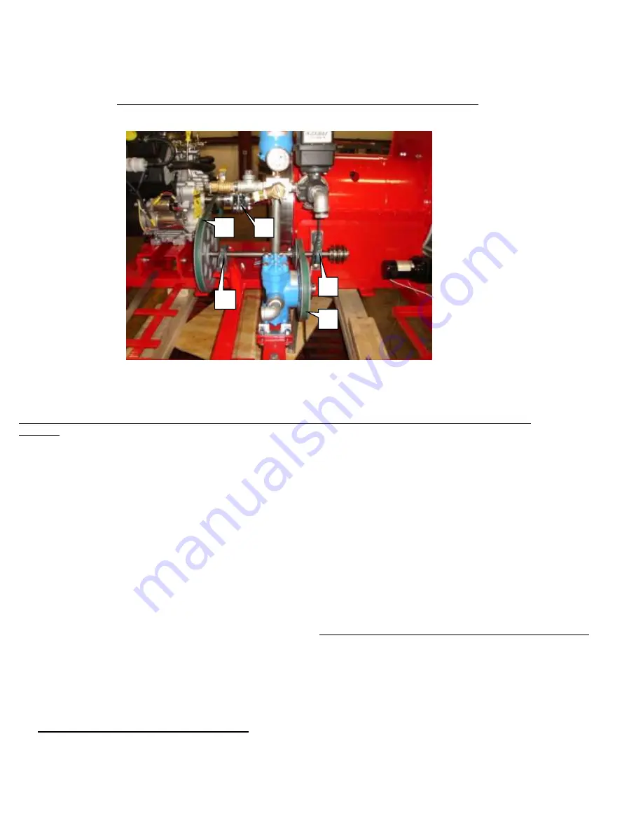
Belt Tension
Efficient machine operation requires that the belts always be properly tensioned.
V -belts 6930 and 6945 are used to drive the Hypro pump (shown below).
To adjust belt #1 (6945), loosen bolts on bearing #3 then move bearing in the direction of the arrow. Tighten bolts securely
and check for proper tension.
To adjust belt #2 (6930), loosen pump mounting bolts at the base of the pump and move in the direction of the arrow. Tighten
bolts securely and check for proper tension.
Always check the pulleys and jack shaft alignment after any adjustments are made. Replace belts that are broken, worn or
stretched.
7.5
Changing the Belts
After using the Model CS4 for a long period of time, the belts will stretch and wear. To change belts, follow this procedure:
1.
Turn off engine and remove key for
SAFETY
. Remove the guards around belt and pulleys.
2.
Refer to the picture section 7.4 for changing the belts. To replace belt #1 (6945), loosen bearing #3 then slide the bearing toward the
output shaft of the engine. The center section of the coupling (#5) will have to be removed in order to remove the old belt and install a
new one. Page 28 has a detailed picture of the coupling. The center section of the coupling must be disassembled and assembled with
extreme care. Damage to the coupling can result in premature bearing failure in the turbine and engine. A new bolt kit for the coupling is
recommended before reassembling the coupling. ALWAYS USE TOPLOC NUTS. Remove the bolts from the coupling (2 ea. side of
flange). Loosen setscrews on one flange only. A thread lock material is used on the threads at assembly. Heat may be needed to break that
bond. Clean all dirt and rust that has accumulated on the shaft (behind the flange) then slowly wedge the center section off of the flange.
Note: The flanges are counter bored to match the flange bushings. Once the center section is removed, belt #1 can be removed and a new
belt can be installed. DO NOT TENSION THE BELT UNTIL THE CENTER SECTION OF THE COUPLING IS INSTALLED. Bolt
the center section per the picture on page 28.DO NOT TIGHTEN THE SET SCREWS AT THIS TIME. Note position of bolts and
locking nuts. Once the coupling is installed and securely tightened, check to see if the key is in position on the shaft and in the keyway of
the flange. Coat the setscrews with Loc Tite (red) and securely tighten. Re check all the setscrews and coupling bolts before proceeding.
3.
To replace belt #2 (6930), loosen mounting bolts (#5) under the Hypro pump and slide toward the Turbine. Remove old belt then
install the new belt. Adjust the belt tension by sliding the pump assembly away from the Turbine Assembly. See section 4.2.1. in the
previous section for more information. Check the pulley alignment and recheck both belts and the tightness of all bolts and set screws.
ASSEMBLE ALL GUARDS BEFORE OPERATING UNIT!
4.
To replace (4L870) Granular Bin belts (optional Granular models only) remove granular bin cover. Remove two 3/8” bolts on
jackshaft right side bearing. Slide old belts off. Replace with new belts and reinstall two 3/8” bolts in pillow block, apply pressure straight
down on jackshaft to give proper belt tension and tighten pillow block bolts. Reinstall guards.
5.
Install all guards before operating blower unit!
1
5
4
2
3
Summary of Contents for BT-CS4
Page 11: ...11 4 4 MODEL BT CS4 Assembly Instructions ...
Page 12: ...12 ...
Page 21: ...21 ...
Page 22: ...22 ...
Page 23: ...23 ...
Page 24: ...24 ...
Page 25: ...25 ...
Page 26: ...26 ...
Page 27: ...27 ...
Page 28: ...28 ...
Page 29: ...29 ...
Page 30: ...30 ...
Page 31: ...31 ...
Page 32: ...32 ...
Page 33: ...33 ...
Page 34: ...34 ...


