PRC5 – Wavefolder
The Wavefolder is a powerful processor which adds overtones to input waveforms. Typical operation
would begin with a simple waveform input – for example, input a sine-wave and as you increase the
Folds dial the waveform folds back on itself to produce overtone frequencies. But the folding effect can
also be used to process more complex input signals - think of it as a unique distortion device.
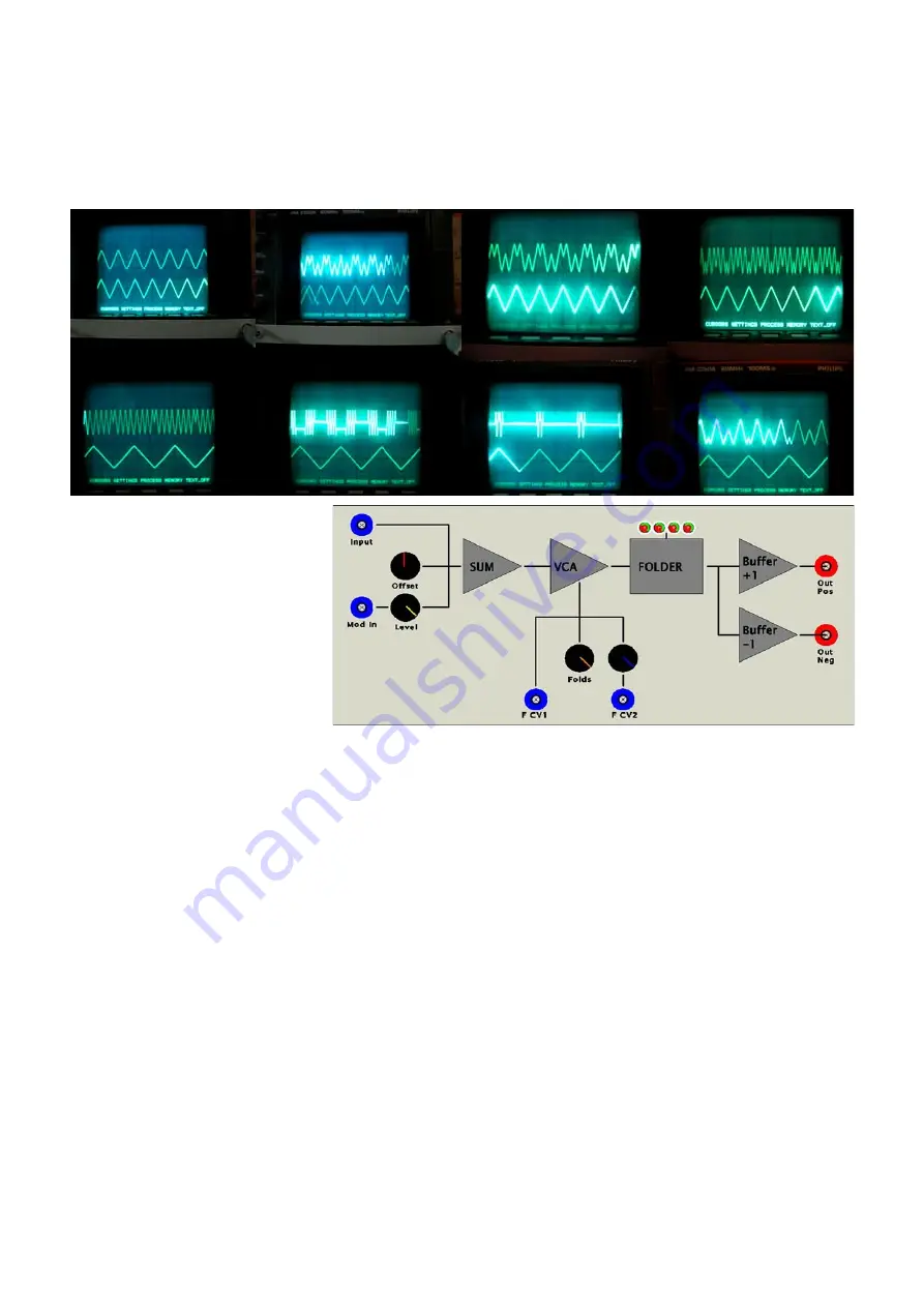
The PRC5 can be better
understood with reference to the
Block diagram. At the top there
are two signal inputs plus an
Offset control - the main input is
un-attenuated, while there is a
secondary input with level control.
I consider the un-attenuated input
to be the 'main' input because the
module is set up to expect typical
+/-5V bipolar signals. Both inputs
are DC coupled and this is notable both for the fact that LFO waveforms can be processed and that
applying DC offsets can really alter the resulting waves. A DC offset can either be applied with the
Offset dial (centre equals zero offset) or I will typically apply an LFO to the 2nd input and use the level
control to dial in a little of this - the result sounds somewhat similar to pulse-width modulation. (eg. Try
this with DC generated from the CTL2 Joystick)
The input summer is followed by an internal VCA (linear response) which feeds the central Folder
circuit. The VCA goes from zero output with the Folds dial fully counter-clockwise and with the first little
turning of the Folds dial (or external CV) the response is exactly like a regular VCA. But the interest
comes when the output r/-5V boundary points (roughly 9 or 10 o'clock on the dial) - once
pushed beyond these points, the waveform direction reverses (folds). Further amplification results in the
folded waveform again reaching the boundary points, but this time going in the opposite direction -
again going beyond this point results in another reversal of direction. There are a total of four folds
possible - indicated by the four bi-colour LED indicators (which actually achieve the folding behaviour).
Beyond the fourth fold the waveform peaks begin to flatten out. There are two CV inputs to modulate
the Folds amount - the top one (FCV1) is unattenuated while the lower one (FCV2) has a level control.
The action of applying a DC offset basically pushes the waveform in one direction so that it bumps into
one of the +/-5V boundaries earlier than the other. Modulating this offset achieves interesting tonal
shifts. All inputs respond from DC up to high frequencies - interesting effects can be achieved i) mixing
two audio signals at the two inputs & ii) modulating the Folds level with an audio rate signal.
There are two outputs, both of which give output signals ranging from -5V to +5V. The Neg output is
simply an inverted copy of the Pos output. It should be noted that input waveforms should be anything
except for squarewaves - these make no sense to the Wavefolder!


