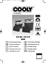
CP10.241, CP10.241-C1, CP10.241-S1,
CP10.241-S2, CP10.242
CP-Series
24V,
10A,
240W,
S
INGLE
P
HASE
I
NPUT
Aug. 2017 / Rev. 1.4a DS-CP10.241-EN
All values are typical at 24V, 10A, 230Vac, 50Hz, 25°C ambient and after a 5 minutes run-in time unless otherwise noted.
www.pulspower.com Phone +49 89 9278 0 Germany
I
NDEX
Page
Page
1.
Intended Use .......................................................3
2.
Installation Requirements...................................3
3.
AC-Input...............................................................4
4.
DC-Input...............................................................5
5.
Input Inrush Current ...........................................6
6.
Output .................................................................7
7.
Hold-up Time.......................................................8
8.
DC-OK Relay Contact ..........................................9
9.
Efficiency and Power Losses..............................10
10.
Lifetime Expectancy ..........................................11
11.
MTBF ..................................................................11
12.
Terminals and Wiring........................................12
13.
Functional Diagram...........................................13
14.
Front Side and User Elements...........................14
15.
EMC....................................................................15
16.
Environment ......................................................16
17.
Protection Features ...........................................17
18.
Safety Features ..................................................17
19.
Dielectric Strength ............................................18
20.
Approvals...........................................................19
21.
Other Fulfilled Standards..................................19
22.
Physical Dimensions and Weight ..................... 20
23.
Accessories ........................................................ 21
23.1.
ZM4.WALL – Wall/Panel Mount Bracket .21
23.2.
ZM12.SIDE - Side Mounting Bracket........22
23.3.
YR20.242 - Redundancy Module..............23
23.4.
YR20.246 - Redundancy Module with
Automated Load Sharing ....................................23
24.
Application Notes............................................. 24
24.1.
Peak Current Capability ...........................24
24.2.
Back-feeding Loads ..................................25
24.3.
External Input Protection.........................25
24.4.
Output Circuit Breakers............................25
24.5.
Series Operation .......................................26
24.6.
Parallel Use to Increase Output Power....26
24.7.
Parallel Use for Redundancy ....................27
24.8.
Inductive and Capacitive Loads................28
24.9.
Charging of Batteries ...............................28
24.10.
Operation on Two Phases ........................29
24.11.
Use in a Tightly Sealed Enclosure ............29
24.12.
Mounting Orientations ............................30
The information given in this document is correct to the best of our knowledge and experience at the time of
publication. If not expressly agreed otherwise, this information does not represent a warranty in the legal sense of the
word. As the state of our knowledge and experience is constantly changing, the information in this data sheet is
subject to revision. We therefore kindly ask you to always use the latest issue of this document (available under
www.pulspower.com).
No part of this document may be reproduced or utilized in any form without our prior permission in writing.
T
ERMINOLOGY AND
A
BREVIATIONS
PE and
symbol
PE is the abbreviation for
P
rotective
E
arth and has the same meaning as the symbol
.
Earth, Ground
This document uses the term “earth” which is the same as the U.S. term “ground”.
T.b.d.
To be defined, value or description will follow later.
AC 230V
A figure displayed with the AC or DC before the value represents a nominal voltage with
standard tolerances (usually ±15%) included.
E.g.: DC 12V describes a 12V battery disregarding whether it is full (13.7V) or flat (10V)
230Vac
A figure with the unit (Vac) at the end is a momentary figure without any additional
tolerances included.
50Hz vs. 60Hz
As long as not otherwise stated, AC 100V and AC 230V parameters are valid at 50Hz mains
frequency. AC 120V parameters are valid for 60Hz mains frequency.
may
A key word indicating flexibility of choice with no implied preference.
shall
A key word indicating a mandatory requirement.
should
A key word indicating flexibility of choice with a strongly preferred implementation.
2/30


