CU-EMA+
– Clean cleaning nest (hole inside the cooler block), as the heat exchangers are installed with silicone grease.
– Purge the heat exchanger until all contaminants have been removed.
– Grease the cooled outside surface external surface with silicone grease.
– Reinsert the heat exchanger into the cooling nest with a rotating movement.
– Reconnect the gas supply and condensate drain. The gas inlet is marked red.
– Restore power/gas supply and wait for unit to be ready for operation.
7.6 Replacing the Microfuse for the Expansion Module/Regulator
– Close gas supply.
– Switch off and unplug the device (also applies to external controller voltage).
– After shutting off the power, allow a discharge time of at least 5 seconds.
– Unscrew the metal cover between the lower conduit to access the board.
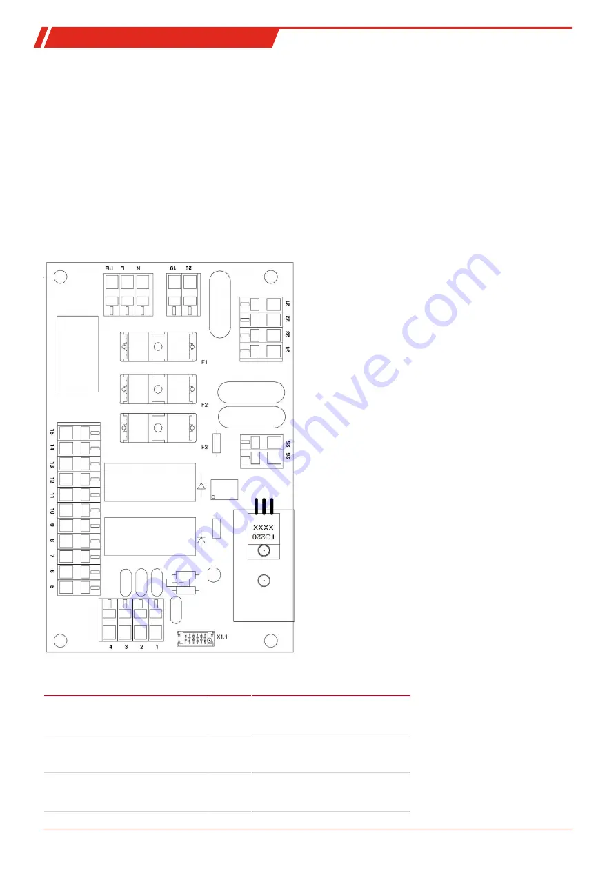
– Replace microfuse (pos. F1, F2 or F3).
Fig. 2: Add-on electronics wiring diagram
No.
Function
Fusing
F1
Main unit + pumps
0.5 A
delayed
action
F2
self-regulating, heated line
8 A
delayed
action
(for built-in regulator use 63 mA
delayed action)
F3
Built-in regulator
8 A
delayed
action
(for self-regulating heated line use
63 mA delayed action)
26
Bühler Technologies GmbH
BE440029 ◦ 10/2020


