TC-MIDI (+)
If the display flashes during operation or an error message ap-
pears, please refer to bullet “Troubleshooting”.
Please refer to the data sheet for performance data and max-
imum ratings.
5.1 Description of functions
The cooler is controlled by a microprocessor. With the factory
preset the control already incorporates the various character-
istics of the built-in heat exchangers.
The programmable display shows the block temperature in
the selected display unit (°C / °F) (factory preset °C). Applica-
tion-specific settings can easily be configured guided by the
menu, using the 5 buttons. For one, this applies to the target
outlet dew point, which can be set from 2 to 20 °C (36 °F to
68 °F) (factory preset 5 °C/41 °F).
And then the warning thresholds can be adjusted for low and
excess temperature. These are set relative to the outlet dew
point
τ
a
setting.
For the low temperature the range is
τ
a
-1 to - 3 K (at a min-
imum 1 °C/ 34 °F cooling block temperature), for the excess
temperature the range is
τ
a
+1 to +7 K. The factory presets for
both values are 3 K.
The flashing display and the status relays indicate the condi-
tions are below or above the configured warning range (e.g.
after switching on).
The status output can e.g. be used to control the sample gas
pump to allow for the gas flow to only be switched on once
the permissible cooling range has been reached or shut off the
pump in the event of a moisture detector alarm.
The separated condensate can be drained via connected peri-
staltic pumps or add-on automatic condensate drains.
Fine mesh filters can also be used, which in turn can be in-
stalled in optional moisture detectors.
The glass dome allows the dirt level of the filter element to
easily be determined.
The moisture detector is easy to remove. This may be required
if a condensate enters the cooler due to a malfunction and the
peristaltic pump or the automatic condensate drain is unable
to remove it.
A P1 gas pump can be attached to the gas cooler, optionally
also with bypass valve for regulating the flow. This allows the
sample gas pump to be expanded by a single-leg system, so
when equipped with a single heat exchanger or for the re-
spective application the two gas paths of the dual heat ex-
changers are switched in series, for example Cooling 1 – Pump
– Cooling 2.
5.2 Use of menu functions
Brief description of the operating principle:
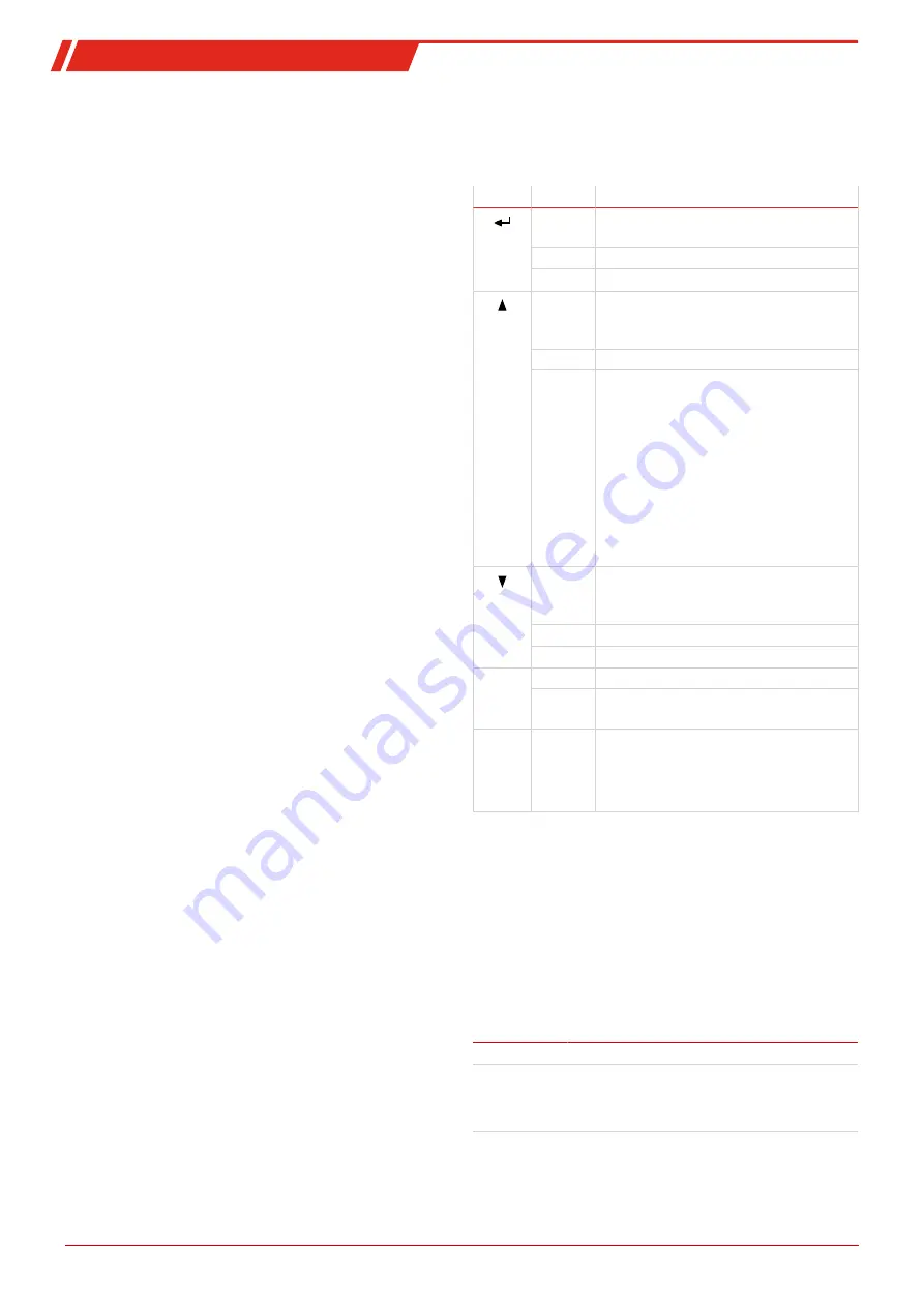
The unit is operated using 5 keys. Their functions are:
Button
Section
Functions
or
OK
Display
• Switches from the measurement dis-
play to the main menu
Menu
• Selects the menu item displayed
Enter
• Applies an edited value or a selection
Display
• temporarily switches to the alternat-
ive measurement display (if option
installed)
Menu
• Back
Enter
• Increase value or browse selection
• Note:
▪ Press button 1 x = changes para-
meter / value by one;
▪ Hold button = fast mode (numer-
ical values only)
▪ Display flashes: modified para-
meter/value
▪ Steady display: original display/
value
Display
• temporarily switches to the alternat-
ive measurement display (if option
installed)
Menu
• Next
Enter
• Reduce value or browse selection
ESC
Menu
• Move one level up
Enter
• Return to menu
Changes will not be saved!
F
or
Func
• Sets a menu to favourite.
(Note: The favourite menu will also
be activated with the menu locked!)
5.2.1 Lock Menu
Some menus can be locked to prevent inadvertently changing
the settings of the unit. This requires setting a code. For in-
formation on setting up or disabling the menu lock please
refer to "Global Settings" (toP) under menu item toP > Loc.
The menu lock is not enabled at the time of delivery, all menu
items can be accessed.
With the menu locked, only the following menu items will be
visible without entering the correct code:
Menu item
Explanation
toP > unit
Temperature unit selection (°C or °F).
F or Func.
Accessing the Favourites menu
NOTICE! This menu may be one that is nor-
mally locked.
15
Bühler Technologies GmbH
BX440016 ◦ 09/2021


