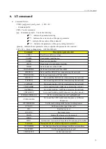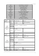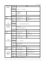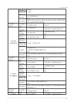
S3-915M
User manual
6
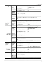
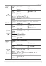
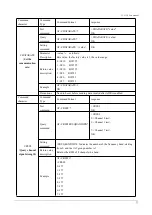
ground
11
ANT
Antenna interface, stamp hole (50 ohm characteristic
impedance)
12
GND
Ground wire, connected to the power reference
ground
13
GND
Ground wire, connected to the power reference
ground
14
GND
Ground wire, connected to the power reference
ground
15
GND
Ground wire, connected to the power reference
ground
16
XRES
Input
External reset pins
17
ADC_IN
Input
NC (reserved pin)
18
AUX
Input/output
NC (reserved pin)
19
SETA
Input/output
NC (reserved pin)
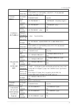
20
UART_RX
Input/output
UART RX pin
21
UART_TX
Input/output
UART TX pin
22
SWD_DATA
Input/output
SWD Data pin
23
SWD_CLK
Input/output
SWD Clock pin
24
GND
Ground wire, connected to the power reference
ground
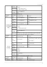
25
SPI_MISO
Input/output
SPI MISO test point, internally connected, cannot be
used as external SPI
26
SPI_NSS
Input/output
SPI NSS test point, internally connected, cannot be
used as an external SPI
27
SPI_MOSI
Input/output
SPI MOSI test point, internally connected, cannot be
used as an external SPI
28
SPI_SCK
Input/output
SPI SCK test point, internally connected, cannot be
used as external SPI
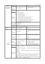
★
For the pin definition, software driver and communication protocol of the module, please refer to ASR
official
《
ASR6501 Datasheet
》 ★
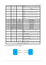
3.3 Recommended connection diagram


