Respirator
Assembly
20
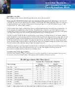
Installing Headband into
Helmet
1. Turn helmet and headband suspension
upside down.
2. Place headband inside helmet with brow pad
facing front of shell.
3. Insert keys into respective key slots. Push
firmly until keys snap into place (Figure 8).
Using the GVXCS Chin Strap
1. Attach chin strap to headband by sliding chin
strap keyway slot over plastic head on button
inside the inner shell. Refer to GVXCS chin strap installation instructions.
2. Put helmet on your head. Adjust chin strap length with the plastic slide.
Optional Lens Covers
1. If desired, apply optional lens covers designed to protect the respirator’s
plastic lens. Apply up to 5 lens covers at a time.
2. When lens becomes soiled, remove by pulling tab at edge of lens cover
to clear your vision.
Optional Cheek Pad Assembly
1. Remove plastic from the Velcro attached to the cheek pad. Apply to the
helmet. Press firmly, holding pad in place to ensure a secure placement
(Figure 10).
2. Repeat steps for the opposite side.
Attaching Cape to Helmet
1. Place cape on table or workbench. (Figure 4, page 19)
2. With window frame open, place helmet on top of cape.
3. Line up plastic tab on the cape over the breathing tube connection
(Figure 11).
NOTE
Installation must begin with tab in the back of the helmet.
4. Ease cape rim completely into the groove along helmet edge, working
your way to the front. Be certain cape is completely in place at every
point along helmet’s bottom edge.
5. Snap the clamp to tighten cable and hold cape snugly on helmet, while
ensuring the cape stays in the groove. Latch should be centered in the
front, below the chinguard (Figure 12).
6. Close and latch window frame.
7. Pull quickly and forcefully on the cape to ensure proper assembly.
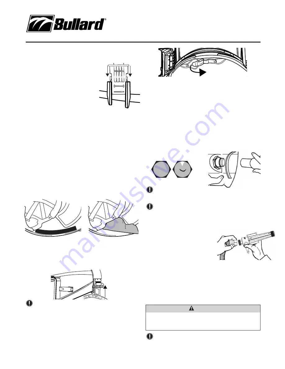
Installing Breathing Tube Assembly onto
Respirator Helmet
1. Prior to connecting the breathing tube, ensure foam is present/properly
inserted into the black threaded connector (Figure 13). Inspect for any
gaps between foam and side wall.
2. Inspect each end of the breathing tube to ensure the red washers are
installed inside the threaded fittings.
3. Connect breathing tube assembly to helmet by screwing plastic hose
connector to fitting located on the rear of the helmet. Turn clockwise to
tighten (Figure 14).
NOTE
Do not remove foam from inside the breathing tube. The foam
helps reduce the noise level of the incoming air.
NOTE
If the red washers are no longer present in the breathing tube
threaded fittings, install immediately (Part Number: GVXBTW).
Using Climate Control Devices
GenVX Series respirators are approved by
NIOSH for use with optional Bullard climate
control devices: CT Series, DC50 Series, HCT
Series, Frigitron 2000 Series, AC1000, and
HC2400 Series.
1. Follow the instructions supplied with your
climate control device.
2. Be sure to use only the GenVXBT with your climate control device.
3. Screw nylon hose connector on end of breathing tube to hose thread on
climate control device.
4. Firmly tighten hose connector by hand (Figure 15).
5. Lace belt supplied with respirator through belt loop bracket on climate
control device.
NOTE
The AC1000 cover sleeve at the bottom of the cylinder may
become loose. Immediately remove the knob at the end of the
cylinder and tighten the retaining nut with a spanner wrench.
Figure 8
WARNING
Only use climate control devices manufactured by Bullard. Substituting
other climate control devices will void the NIOSH approval and could
result in death or serious injury.
Figure 15
Figure 14
Figure 9
Figure 10
Figure 11
Figure 12
Figure 13
Correct
Incorrect