4
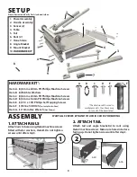
Back Stroke Stop
M16 x 50 Bolt
Cam Shaft
Han
dle
Asse
mbl
y
set up
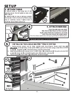
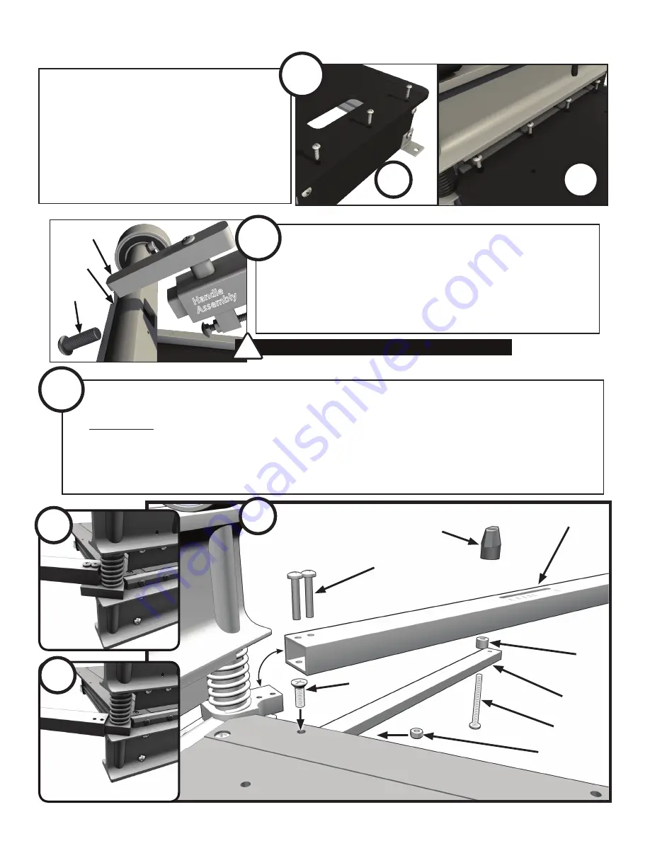
3. attach table
a.
Attach table to tail using
Item E
self
tapping screws. Do not tighten screws until
after step B.
B.
Attach table to base working outward
from center. Start all screws by hand, using
Item D
machine screws. Tighten
Item D
machine screws from center out.
3
3b
3a
4. attach hanDle:
insert handle into cam shaft.
Note: Backstroke Stop must face upward!
Tighten
Item F
Bolt (pre-installed in cam shaft)
with 10mm hex wrench
Item G
(Included).
Note: Do not remove plastic tie and orange tag until handle is bolted in place.
Handle under extreme pressure
- do not allow to slam back!
!
4
b
c
d
e
f
j
g
h
a
Fence
mounts on
top oF pivot
piVot
Fence
Y
YES
pivot Does not
inseRt into Fence
this is Wrong!
Z
NO!
installing tHe angleMaster™ fence systeM
1. Swing corner pivots out to align parallel with head beam. Fasten both fences
a
oN ToP oF corresponding corner pivots
b
(See picture Y below) using screws M6 x 35 PHP
screws
c
. orient fence
a
so that the slot is away from the table.
2. Attach struts
d
to table using ¼-20 x 1¼ FHP screws
e
and locknuts
e
. Thread ¼-20 x 2¾ PHP
screws
f
into struts
d
and up through spacer
g
and slots in fences
a
.
3. Thread knobs
h
onto screws
f
and tighten at desired angle.
5
5a
5b
5c


