background image

MY21B01 - 12_1.0_25.06.2020

14

Overview

3

Overview 

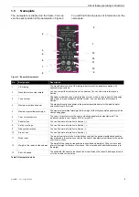
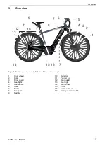
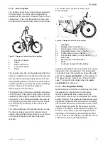
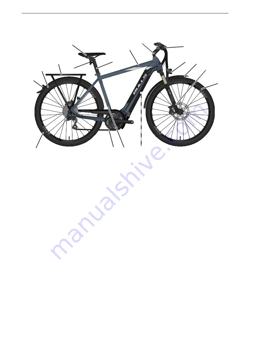
Figure 2: Pedelec viewed from right, Bull Cross Rider used as example 

1

Front wheel

2

Fork

3

Front guard

4

Headlight

5

Handlebars

6

Stem

7

Frame

8

Seat post

9

Saddle

10

Reflector

11

Pannier rack

12

Rear guard 

13

Rear light

14

Rear wheel

15

Chain

16

Frame number

17

Battery and nameplate

1

2

3

4

5

6

7

8

9

10

11

12

13

14

15 16 17

Summary of Contents for 21-15-1016

Page 1: ... Reichweite AMM PMWH MIN MPH KM H RESET T U R B O S P O R T S T O U R E C O O F F MPH KM H Reichweite AMM PMWH M IN M PH K M H BULLS Cross Mover Evo 1 BULLS Cross Mover Evo 2 BULLS Cro ss Ride r Evo 1 Münch en BULL S Cross Ri der Evo 2 Cologn e BUL LS Cross Street E1 21 15 1016 21 15 1018 21 15 1027 21 15 1028 21 15 1069 21 15 1070 21 17 1013 21 17 1015 21 17 1029 21 17 1030 21 17 1045 21 17 1064 ...

Page 2: ...on fork 15 3 1 2 3 Steel suspension fork 16 3 1 3 Brake system 16 3 1 3 1 Disc brake 16 3 1 4 Drive system 17 3 1 5 Rechargeable battery 17 3 1 5 1 Frame battery 18 3 1 5 2 Pannier rack battery 19 3 1 5 3 Integrated battery 19 3 1 6 Display 20 3 1 7 Control panel 20 3 1 7 1 USB port 20 3 1 8 Riding light 20 3 1 9 Charger 20 3 2 Proper use 21 3 2 1 Maximum permitted total weight 22 3 2 2 Data priva...

Page 3: ...sition 52 6 5 2 Adjusting the handlebars 53 6 5 3 Adjusting the stem 53 6 5 3 1 Adjusting the height of the handlebars 53 6 5 3 2 Adjusting the quick release clamping force 53 6 5 4 Retracting the brake linings 53 6 5 5 Adjusting the Suntour fork 54 6 5 5 1 Adjusting the negative deflection 54 6 5 5 2 Adjusting the steel suspension fork negative deflection 54 6 6 Accessories 55 6 6 1 Child seat 55...

Page 4: ...ables 77 7 4 7 Checking the gear shift 77 7 4 8 Checking the stem 77 7 4 9 Checking the USB port 77 7 4 10 Checking the chain tension 77 8 Maintenance 78 8 1 Suspension system 79 8 1 1 Rear frame damper 79 8 1 2 Suspension fork 80 8 1 3 Suspension seat post 81 8 2 Axle with quick release 81 8 2 1 Checking the quick release 82 8 3 Maintaining the stem 82 8 4 Adjusting the gear shift 82 8 4 1 Cable ...

Page 5: ...are out riding www bulls de service downloads Copyright ZEG Zweirad Einkaufs Genossenschaft eG Distribution or reproduction of these operating instructions and utilisation or communication of their content is prohibited unless expressly approved Any infringement will render the offender liable for compensation All rights reserved in the event that a patent utility model or industrial design is reg...

Page 6: ...ectives The operating instructions comply with the essential requirements specified in Machinery Directive 2006 42 EC Electromagnetic Compatibility Directive 2014 30 EU ISO 20607 2018 Safety of machinery Instruction handbook General drafting principles EN 15194 2018 Cycles Electrically power assisted cycles pedelec bicycles EN 11243 2016 Cycles Luggage carriers for bicycles Requirements and test m...

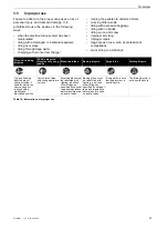
Page 7: ...s to take any action Stylised form Use Italics Glossary term Underlined in blue Link Underlined in grey Cross references Check marks Requirements Triangle Instruction for action 1 Instruction for action Several instructions for action in specified order Result of the action SPACED Indicators on the display screen Bulleted lists Only applies to pedelecs with this equipment Each type has a different...

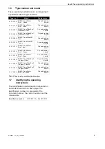
Page 8: ...aggage 6 Year of manufacture The year of manufacture is the year in which the pedelec was manufactured The production period is from August 2019 to July 2020 7 Pedelec type You can find more information in Section 3 2 8 Safety markings You can find more information in Section 1 4 9 Disposal instructions You can find more information in Section 10 10 Area of use You can find more information in Sec...

Page 9: ...BULLS Cross Rider Evo 1 München Gent 21 15 1028 BULLS Cross Rider Evo 1 München Trapez 21 15 1069 BULLS Cross Street E1 Gent 21 15 1070 BULLS Cross Street E1 Trapez 21 17 1013 BULLS Cross Mover Evo 2 Gent 21 17 1014 BULLS Cross Mover Evo 2 Trapez 21 17 1015 BULLS Cross Mover Evo 2 Wave 21 17 1029 BULLS Cross Rider Evo 2 Cologne Gent 21 17 1030 BULLS Cross Rider Evo 2 Cologne Trapez 21 17 1045 BULL...

Page 10: ... fire and explosion due to short circuit in the battery Metal objects may connect the battery s electrical terminals The battery may self ignite and explode Never insert paper clips screws coins keys and other small parts into the battery Chargers with excessive voltage damage batteries This may result in fire or an explosion Only use batteries approved for the pedelec Clearly label the supplied c...

Page 11: ...per or the suspension fork Avoid contact with skin 2 2 3 Defective battery Liquids and vapours may leak from damaged or faulty batteries Excessively high temperatures may also cause liquids and vapours to leak from the battery Such liquids and vapours can irritate the airways and cause burns Never dismantle the battery Avoid contact with skin Do not inhale vapours 2 3 Requirements for the rider Th...

Page 12: ...he event of pain or discomfort After contact with eyes Rinse eyes under flowing water for at least ten minutes with the lids open also rinse under lids Immediately consult a doctor in case of any pain or discomfort After swallowing Rinse out mouth with water Never induce vomiting Risk of aspiration If a person is lying on their back and vomiting place them in the recovery position Seek medical adv...

Page 13: ...rmed or starts to emit smoke 2 If charging remove the plug connector from the socket 3 Contact the fire service immediately Use Class fire extinguishers to put out the fire Never extinguish damaged batteries with water or allow them to come into contact with water Inhaling vapours can cause intoxication Stand on the side of the fire where the wind is blowing from Use breathing apparatus if possibl...

Page 14: ...l Cross Rider used as example 1 Front wheel 2 Fork 3 Front guard 4 Headlight 5 Handlebars 6 Stem 7 Frame 8 Seat post 9 Saddle 10 Reflector 11 Pannier rack 12 Rear guard 13 Rear light 14 Rear wheel 15 Chain 16 Frame number 17 Battery and nameplate 1 2 3 4 5 6 7 8 9 10 11 12 13 14 15 16 17 ...

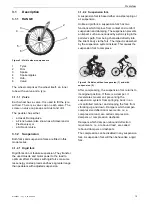
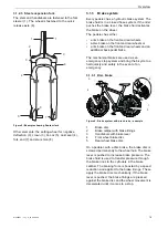
Page 15: ...based either on a steel spring or air suspension Unlike a rigid fork a suspension fork has two functions which improve floor contact and comfort suspension and damping The suspension prevents an impact such as one caused by a stone lying in the pedelec s path from being channelled directly into the rider s body via the fork The impact is absorbed by the suspension system instead This causes the su...

Page 16: ...ck pedal brake The mechanical brakes are used as an emergency stop system and bring the bicycle to a halt quickly and safely in the event of an emergency 3 1 3 1 Disc brake Figure 6 Brake system with disc brake example 1 Brake disc 2 Brake calliper with brake linings 3 Handlebars with brake lever 4 Front wheel brake disc 5 Rear wheel brake disc On a pedelec with a disc brake the brake disc is scre...

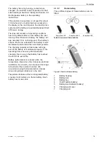
Page 17: ... has been reached The electric drive system is made up of 8 components Figure 8 Diagram of electric drive system 1 Headlight 2 Display more in Section 3 1 6 3 Control panel more in Section 3 1 7 4 1 Integrated battery more in Section 3 1 5 3 4 2 Frame battery more in Section 3 1 5 1 4 3 Pannier rack battery more in Section 3 1 5 2 5 Rear light 6 Electric gear shift alternative 7 Motor A charger de...

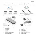
Page 18: ...ure The charging capacity will decrease with age even if the battery is maintained properly If the operating time is severely shortened after charging this is a sign that battery has reached the end of its useful life Battery performance is reduced when the temperature drops since this increases electrical resistance As a result you can expect the range to be shorter than normal in winter We recom...

Page 19: ...ery key 6 Battery level indicator battery 7 On Off button battery 3 1 5 3 Integrated battery Three different types of pannier rack batteries can be fitted Figure 12 Overview of frame batteries Figure 13 Integrated battery in detail 1 Battery key 2 Retainer guard 3 Securing hook 4 On Off button battery 5 Battery level indicator battery 6 Battery housing PowerPack 300 PowerPack 400 PowerPack 500 1 2...

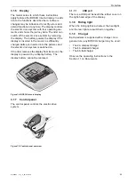
Page 20: ...rom its mount the display is powered by a display battery The display battery cannot be replaced Figure 14 BOSCH Intuvia display 3 1 7 Control panel The control panel controls the electric drive system Figure 15 Control panel overview 3 1 7 1 USB port There is a USB port beneath the rubber cover on the right hand edge of the display 3 1 8 Riding light When the riding light is activated the headlig...

Page 21: ...se requires the appropriate training in particular riding in bends and braking should be practised The strain on the rider in particular the hands and wrists arms shoulders neck and back is accordingly high Inexperienced riders tend to brake excessively and lose control as a result A racing bicycle is designed for fast rides on roads and paths with a good undamaged road surface A racing bicycle is...

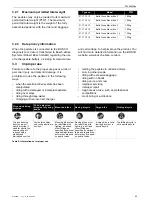
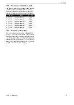
Page 22: ...h excessive baggage riding with no hands riding on ice and snow improper servicing improper repair tough areas of use such as professional competitions stunt riding or acrobatics Type no Model PTW 21 17 1013 Bulls Cross Mover Evo 2 150 kg 21 17 1014 Bulls Cross Mover Evo 2 150 kg 21 17 1015 Bulls Cross Mover Evo 2 150 kg 21 17 1016 Bulls Cross Mover Evo 1 150 kg 21 17 1017 Bulls Cross Mover Evo 1 ...

Page 23: ...se requires the appropriate training in particular riding in bends and braking should be practised The strain on the rider in particular the hands and wrists arms shoulders neck and back is accordingly high Inexperienced riders tend to brake excessively and lose control as a result A racing bicycle is designed for fast rides on roads and paths with a good undamaged road surface A racing bicycle is...

Page 24: ...ons stunt riding or acrobatics City and trekking bicycles Child s bicycles bicycles for young adults Mountain bikes Racing bicycle Cargo bike Folding bicycle City and trekking bicycles are not sports bicycles If used for sports the rider can expect reduced riding stability and diminished comfort Cycles for children and young adults are not toys Mountain bikes must be retrofitted with lighting a be...

Page 25: ...sis tool data is transferred to Bosch eBike Systems Robert Bosch GmbH regarding the use of rechargeable battery including its temperature and cell voltage to help improve the product You will find more detailed information on the BOSCH website www bosch ebike com en Type no Model PTW 21 17 1013 Bulls Cross Mover Evo 2 150 kg 21 17 1014 Bulls Cross Mover Evo 2 150 kg 21 17 1015 Bulls Cross Mover Ev...

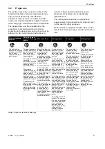
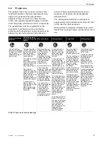
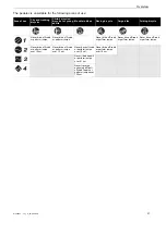
Page 26: ...hnical data Area of use City and trekking bicycles Child s bicycles bicycles for young adults Mountain bikes Racing bicycle Cargo bike Folding bicycle Suitable for tarmacked and paved roads Suitable for tarmacked and paved roads Suitable for tarmacked and paved roads Suitable for tarmacked and paved roads Suitable for tarmacked and paved roads Suitable for tarmacked roads cycle paths and firm grav...

Page 27: ...ever drive off road or perform jumps Never drive off road or perform jumps Never drive off road or perform jumps Never drive off road or perform jumps Never drive off road or perform jumps over 15 cm Never drive off road or perform jumps over 15 cm Never drive off road or perform jumps over 15 cm Never drive off road or perform jumps over 15 cm Never ride downhill or perform jumps over 61 cm Never...

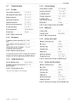
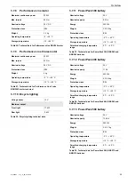
Page 28: ...rms 2 5 m s Highest effective value of weighted acceleration for the entire body 0 5 m s Table 14 Emissions from the pedelec Axle nut tightening torque 35 Nm 40 Nm Handlebars clamping screw maximum tightening torque 5 Nm 7 Nm Table 15 Tightening torque values Internal lithium ion battery 3 7 V 230 mAh Operating temperature 5 C 40 C Storage temperature 10 C 50 C Charging temperature 0 C 40 C Protec...

Page 29: ...utput Front light 17 4 W Rear light 0 6 W Table 22 Bicycle lighting technical data Nominal voltage 36 V Nominal capacity 8 2 Ah Energy 300 Wh Weight 2 5 2 6 kg Protection class IP54 Operating temperature 5 C 40 C Storage temperature 10 C 40 C Permitted charging temperature range 0 C 40 C Table 23 Technical data for PowerPack 300 BBS245 and BBR245 batteries Nominal voltage 36 V Nominal capacity 11 ...

Page 30: ...ergy 500 Wh Weight 2 9 kg Protection class IP54 Operating temperature 5 C 40 C Storage temperature 10 C 40 C Permitted charging temperature range 0 C 40 C Table 27 Technical data for PowerTube 500 BBP280 horizontal and BBP281 vertical batteries Nominal voltage 36 V Nominal capacity 16 7 Ah Energy 625 Wh Weight 3 5 kg Protection class IP54 Operating temperature 5 C 40 C Storage temperature 10 C 40 ...

Page 31: ... the battery is fully charged If the battery level falls below 5 all the LEDs will go out The charge level is also displayed by the battery level indicator battery 3 8 3 Display The display has four buttons and a USB port Figure 18 Overview of the structure of the display s operating elements 1 Display housing 2 Riding light button 3 Info button display 4 RESET button 5 On Off button display 6 Dis...

Page 32: ...es are being charged on a pedelec the function display shows the charging progress for both batteries You can see which of the two batteries is currently being charged by the flashing indicator on the battery Figure 21 The left hand battery is being charged You can also see the battery charge level on the level indicator LEDs battery Level of assistance Use SPORT Powerful assistance for sport ride...

Page 33: ... 3 8 5 9 Additional journey information Only applies to Shimano DI2 automatic hub gears The following additional functions are available on the function display Applies only to eShift with manual Shimano DI2 hub gears The following additional functions are available on the function display Applies only to eShift with Shimano DI2 automatic hub gears The following additional functions are available ...

Page 34: ...n DU XXXX XXXXX Drive system serial number SERVICEMM YYYY Alternative defined inspection date SERV XX KM MI Alternative defined inspection BAT VX X X X Software version 1 BAT VX X X X Software version 2 BAT VX X X X Software version Table 40 System information unvarying indicator Change Start gear This is where you can set the start gear The automatic gear switch function is switched off in Positi...

Page 35: ...to reset the gear shift in the gear shift manufacturer s operating instructions This menu option is only shown when the display is positioned in its mount Gear vx x x x this is the gear software version This menu option is only shown when the display is positioned in its mount This menu option is only shown if you have an electronic control gear Table 43 Changing the system settings indicator Chan...

Page 36: ...the pedelec from the weather conditions with suitable protective covers Transport the battery in a dry clean position where it is protected from direct sunlight 4 3 Storing Store pedelec battery and charger in a clean dry place where they are protected from sunlight Do not store outdoors to ensure a long service life Temperatures under 10 C or over 60 C must generally be avoided Storage at about 1...

Page 37: ...delec battery and charger in a dry clean environment We recommend storing them in uninhabited rooms with smoke alarms Dry locations with an ambient temperature of about 10 C to 20 C are ideal 2 Recharge the display battery for at least 1 hour every 3 months 3 Check the battery level after 6 months If only one LED on the battery level indicator lights up recharge the battery to around 30 60 Notice ...

Page 38: ...d for the first time 1 Press the On Off button battery If none of the LEDs on the battery level indicator light up the battery may be damaged The battery may be fully charged if at least one but not all of the LEDs on the battery level indicator is lit up 5 3 2 Retrofitting a PowerTube Adapter 400 or 500 A PowerTube Adapter 400 or 500 needs to be retrofitted to use a Bosch PowerTube 625 battery 1 ...

Page 39: ...ng the 4 mm hexagon screws 3 Use a ratchet to remove the two 4 mm hexagon screws in the PowerTube adapter Figure 24 Removing hexagon screws 4 Pull out the PowerTube adapter Figure 25 Pulling out the PowerTube adapter 5 Use adapter plates to adjust the distance if necessary Figure 26 Fitted adapter plates 6 Use a TORX T25 wrench to fasten the screws into the battery mount Figure 27 Fastening the ba...

Page 40: ...ntenance tasks for the bicycle in a separate list All assembly work must be completed to ensure the pedelec is ready to ride Complete an assembly report for quality assurance purposes 5 4 1 Installing the wheel in the Suntour fork 5 4 1 1 Screw on axle 15 mm Only applies to Suntour forks with 15 mm screw on axle 1 Insert the axle completely on the drive side Figure 28 Fully inserting the axle 2 Ti...

Page 41: ... by loose quick release axle A faulty or incorrectly installed quick release axle may become caught in the brake disc and block the wheel This will cause a crash Never fit a defective quick release axle Crash caused by faulty or incorrectly installed quick release axle The brake disc becomes very hot during operation Parts of the quick release axle may become damaged as a result The quick release ...

Page 42: ... 5 Check the position and clamping force of the quick release lever The quick release lever must be flush with the lower housing You must be able to see a slight impression on the palm of your hand when you close the quick release lever Figure 38 Perfect position for the clamping lever 6 Use 4 mm hexagon socket spanner to adjust the clamping lever clamping force if required 7 Check the quick relea...

Page 43: ...rrectly installed quick release may become caught in the brake disc and block the wheel This will cause a crash Never fit a defective quick release Crash caused by faulty or incorrectly installed quick release The brake disc becomes very hot during operation Parts of the quick release may become damaged as a result The quick release comes loose This will cause a crash with injuries The front wheel...

Page 44: ...ver is tensioned inadequately or too strongly when closed in the recommended position 1 to 20 mm in front of the fork Setting the quick releases Figure 46 Structure of quick release from rear with 1 axle nut lock and 5 axle nut 1 Record the axle setting value 4 indicated by the directional arrow 3 2 Loosen the axle nut securing screw 2 with a 2 5 mm hex key by approx four revolutions but do not re...

Page 45: ...ft should move in the fork steerer increase the quick release lever tensioning To do so turn the knurled nut slightly in a clockwise direction with the quick release lever open 3 Close the lever and check the stem is firmly in position 5 4 3 3 Checking the headset backlash 1 To check the handlebar headset backlash close the quick release lever on the stem 2 Place the fingers of one hand on the upp...

Page 46: ...sh with injuries Wear sturdy footwear and close fitting clothing WARNING CAUTION Crash caused by difficult to spot damage If the pedelec topples over or you have a fall or an accident there may be difficult to spot damage to components such as the brake system quick releases or frame This may cause a crash with injuries Take the pedelec out of service and have a specialist dealer carry out an insp...

Page 47: ...nce increases as the temperature drops Battery performance is reduced As a result you should expect the range to be shorter than normal in winter Use a thermal protection sleeve on the battery in winter Crash caused by poor road conditions Loose objects such as branches and twigs may become caught in the wheels and cause a crash with injuries Be aware of the road conditions Ride slowly and brake i...

Page 48: ... your specialist dealer if the problem persists 460 Error in USB port 1 Re start the system 2 Contact your specialist dealer if the problem persists Table 47 List of display screen error messages 490 Internal display error Have display checked 500 Battery internal error 1 Re start the system 2 Contact your specialist dealer if the problem persists 502 Fault in the lighting 1 Check the light and it...

Page 49: ...ecialist dealer if the problem persists 610 Voltage error 1 Re start the system 2 Contact your specialist dealer if the problem persists 620 Charger error 1 Replace charger 2 Contact your specialist dealer if the problem persists 640 Internal fault 1 Re start the system 2 Contact your specialist dealer if the problem persists 655 Multiple battery error 1 Switch off system 2 Remove the battery 3 Re...

Page 50: ...tioning Contact your specialist dealer No screen display Internal display error Re start the drive system by switching it on and off Code Description Method of resolution Table 47 List of display screen error messages Code Description Method of resolution If the battery is outside its charging temperature range three LEDs will flash on the battery level indicator 1 Disconnect charger from battery ...

Page 51: ...ng the saddle tilt The saddle tilt must be adjusted to the seat height the saddle and handlebar position and the saddle shape to ensure an optimum fit The seating position can be optimised in this way if needed First adjust the handlebars then the saddle Adjust the saddle tilt to horizontal Figure 48 Horizontal saddle tilt 6 5 1 2 Determining the seat height To adjust the seat height safely either...

Page 52: ...ec near to a wall so that you can lean on the wall to support yourself or ask another person to hold the pedelec for you 1 Climb onto the bicycle 2 Place the pedals into the vertical position with your feet The rider is sitting in the optimal sitting position if the perpendicular line from the kneecap runs through the pedal axle 3 1If the perpendicular line crosses behind the pedal bring the saddl...

Page 53: ... increases over time You therefore need to be aware that the braking force may increase during the wearing in period The same happens after brake pads or discs are replaced 1 Accelerate pedelec to about 25 km h 2 Brake pedelec until it comes to a halt 3 Repeat process 30 50 times The disc brake is retracted and provides optimal braking power Crash caused by incorrectly set clamping force Excessive...

Page 54: ...deflection in the fork Figure 55 Negative deflection setting wheel on the suspension fork crown 1 You will find the negative deflection setting wheel beneath the plastic cover on the crown Remove the plastic cover Turn the negative deflection setting wheel in a clockwise direction to increase the spring pre tensioning Turn the negative deflection setting wheel in an anti clockwise direction to dec...

Page 55: ...ription Article number Protective cover for electrical components 080 41000 ff Panniers system component 080 40946 Rear wheel basket system component 051 20603 Bicycle box system component 080 40947 Parking stand universal stand XX TWO14B Table 49 Accessories Crash caused by incorrect child seat The pannier rack and down tube are unsuitable for mounting child seats and may break Such an incorrect ...

Page 56: ...st dealer makes sure that the fastening mechanism is suitable for the pedelec and that all components are installed and firmly fastened They will also ensure that shift cables brake cables hydraulic lines and electrical cables are adjusted as necessary the rider has optimum freedom of movement and the pedelec s maximum permitted total weight is not exceeded The specialist dealer will provide instr...

Page 57: ...icycle has a hydraulic rim brake check whether the locking levers are fully closed in their final positions Check the front and rear wheel brakes to make sure that they are working properly To do so push the brake levers while stationary to check whether resistance is generated in the usual brake lever position The brake must not lose any brake fluid Check that the riding light is working Check fo...

Page 58: ...er and brake This can lead to a loss of control This may cause a crash with injuries You should practice how to use a loaded pannier rack safely before using the pedelec in public spaces CAUTION CAUTION Crash caused by unsecured baggage Loose or unsecured objects on the pannier rack e g belts may become caught in the rear wheel This may cause a crash with injuries Objects which are fastened to the...

Page 59: ...the battery key from the battery lock see 4 3 Tip the battery into the top section of the frame battery mount until it will go no further There is an audible clicking noise 4 Check the battery to make sure it is firmly in place 6 10 2 Pannier rack battery Only applies to pedelecs with this equipment 6 10 2 1 Removing the pannier rack battery Figure 58 Removing 2 and inserting 3 the pannier rack ba...

Page 60: ...ove the battery from the frame 4 Remove the battery key from the battery lock 6 10 3 2 Inserting the integrated battery Figure 60 Inserting the integrated battery 1 Place the battery into the lower mount with the contacts facing the front see 1 2 Flip the battery up so that the battery is held by the retainer guard see 2 3 Push the battery upwards see 3 There is an audible clicking noise 4 Check b...

Page 61: ...witches automatically between the two batteries several times The charging time is twice as long The two batteries are discharged alternately during use Fire caused by overheated charger The charger heats up when charging the battery In case of insufficient cooling this can result in fire or burns to the hands Never use the charger on a highly flammable surface e g paper carpet etc Never cover the...

Page 62: ...led with an end cap on pedelecs with two batteries Figure 61 Covering open contacts with cover cap example pannier rack battery If you wish to use just one battery on a pedelec which is designed for two batteries cover the contacts in the free slot with the supplied cover cap see 1 otherwise there is a risk of a short circuit caused by the open contacts 6 10 7 Waking the battery The battery switch...

Page 63: ...stance set on the display As soon as the system has been activated ACTIVE LINE PERFORMANCE LINE appears briefly on the display 6 11 2 Switching off the drive system As soon as you stop pushing the pedals in normal mode or reach a speed of 25 km h the drive system switches off the assistance system The assistance system starts up again if you push the pedals and your speed is less than 25 km h The ...

Page 64: ...istraction A lack of concentration while riding increases the risk of an accident This may cause a crash with serious injuries Never allow yourself to be distracted by the display Stop bicycle if you want to make inputs on the display other than a change in level of assistance Only enter data when the bicycle is stationary Notice Do not use display as a handle The display may become irreparably da...

Page 65: ...be a maximum of 6 km h in this case The tractive power of the push assist and its speed can be influenced by the selection of gear To spare the drive first gear is recommended for travelling uphill The level of assistance OFF must not be selected 1 Press the push assist button briefly 2 Press and hold the plus button within 3 seconds to switch on the push assist 3 Release the plus button to shut o...

Page 66: ...splayed and changed no matter whether the display is inserted in the mount or not A few settings are only visible and changeable if the display is inserted A few menu options may be missing depending on the equipment used Press the Info button display and the RESET button together SETTINGS is displayed on the display The System settings is opened Press the info button display repeatedly until the ...

Page 67: ...f they are inserted into the brake disc openings Always keep fingers well away from the rotating brake discs Burns caused by heated brake The brakes may become very hot during operation There is a risk of burns or fire in case of contact Never touch the components of the brake directly after the ride WARNING CAUTION Crash caused by wet conditions The tyres may slip on wet roads In wet conditions y...

Page 68: ...o brake used as an example Push the left hand brake lever to apply the front wheel brake Push the right hand brake lever to apply the rear wheel brake Turn the setting wheel in an anti clockwise direction to increase the rebound speed Turn the setting wheel in a clockwise direction to decrease the rebound speed 1 2 ...

Page 69: ...e lock position if you want the fork to feel stiffer and you are riding on soft ground The positions between OPEN and LOCK provide fine adjustment of compression damping We recommend setting the compression adjuster to the OPEN position first The compression damper controls the speed at which the rear frame damper deflects during slow impact such as smaller impacts or when the rider goes round a c...

Page 70: ... it easier to switch gears and reduces wear on the drivetrain 6 15 1 Using the derailleur gears Only applies to pedelecs with this equipment The speed and range can be increased while applying the same force if you select the right gear Use the derailleur gears Figure 65 Down shifter 1 and up shifter 2 on the left I and right II gear shift Select the appropriate gear with the shifter The gear shif...

Page 71: ...cleaning and preservation of all components at least every six months Clean the charger at least every six months Check USB rubber cover position before each ride Check for tyre wear once a week Check for rim wear once a week Check tyre pressure once a week Check brakes for wear once a month Check electrical cables and Bowden cables for damage and ensure they are fully functional once a month Chec...

Page 72: ...ashing detergent and a toothbrush 4 Service the drive elements after cleaning Crash caused by brake failure The braking effect may be unusually poor temporarily after cleaning servicing or repairs This may cause a crash with injuries Never apply care products or oil to the brake discs or brake linings or the braking surfaces on the rims After cleaning servicing or repair carry out a few test brake...

Page 73: ...on due to penetration by water The battery is only protected from simple spray water Penetration by water can cause a short circuit The battery may self ignite and explode Never clean the battery with a pressure washer water jet or compressed air Keep contacts dry and clean Never immerse the battery in water Never use cleaning agents Remove the battery from the pedelec before cleaning Notice Never...

Page 74: ...rvicing the drive elements 1 Spray the cassette the chain wheels and the front derailleur with a degreasing agent 2 Clean coarse dirt with a brush after soaking for a short time 3 Wash down all parts with dish washing detergent and a toothbrush 4 Treat front and rear derailleur articulated shafts and jockey wheels with Teflon spray 7 3 5 Servicing the pedals Treat pedals with spray oil 7 3 6 Servi...

Page 75: ...edelecs with this equipment The tyre pressure cannot be measured on the simple Dunlop valve The tyre pressure is therefore measured in the filling hose when pumping slowly with the bicycle pump It is recommendable to use a bicycle pump with a pressure gauge The operating instructions for the bicycle pump must be adhered to 1 Unscrew and remove the valve cap 2 Connect the bicycle pump 3 Pump up the...

Page 76: ... pressure in the process The tyre pressure has been adjusted as per the specifications 4 Remove the bicycle pump 5 Screw the valve cap tight 6 Screw the rim nut 1 gently against the rim with the tips of your fingers 7 4 2 Brake system The maintenance interval for the brake depends on the weather conditions and how frequent the bicycle is used If the pedelec is used under extreme conditions such as...

Page 77: ...so needs to be adjusted Medium strength thread locker such as Loctite blue then needs to be applied to the loosened screws and the screws tightened as per specifications Contact your specialist dealer if there is any wear or signs of corrosion 7 4 9 Checking the USB port 7 4 10 Checking the chain tension 1 Check the chain tension in three or four positions turning the crank a full revolution Figur...

Page 78: ...jury due to damaged brakes Special tools and specialist knowledge are required to repair the brakes Incorrect or unauthorised assembly can damage the brakes This may lead to an accident with injuries Only specialist dealers may carry out repairs on brakes Only carry out work or changes such as dismantling sanding or painting which are permitted and described in the brake operating instructions Inj...

Page 79: ...every 200 hours FOX rear frame damper Complete maintenance full interior and exterior inspection damper overhaul air spring overhaul oil change and dust wiper replacement every 125 hours or once a year Suntour rear frame damper Complete shock absorber service including damper reassembly and air seal replacement every 100 hours Injury due to explosion The air chamber is pressurised If the air syste...

Page 80: ... Maintenance of spring and damper unit for Paragon XC 28 XC 30 30 2015 and earlier Recon 2015 and earlier Sektor 2015 and earlier Bluto 2016 and earlier Revelation 2017 and earlier REBA 2016 and earlier SID 2016 and earlier RS 1 2017 and earlier BoXXer 2018 and earlier every 100 hours Maintenance of spring and damper unit for 30 2016 Judy 2018 Recon 2016 Sektor 2016 35 2020 Revelation 2018 Bluto 2...

Page 81: ...mplete maintenance of seat post for Reverb B1 Reverb Stealth B1 every 400 hours Complete maintenance of seat post for Reverb AXS A1 Reverb Stealth C1 every 600 hours All other suspension seat posts Maintenance every 100 hours Crash caused by unfastened quick release A faulty or incorrectly installed quick release may become caught in the brake disc and block the wheel This will cause a crash Insta...

Page 82: ...ase lever position and clamping force Figure 68 Adjusting the quick release clamping force 8 3 Maintaining the stem Incorrectly fastened screws may come loose due to impact The stem may no longer be firmly fixed in its position as a result This will cause a crash with injuries Check the handlebars and the stem s quick release system are firmly in position after the first two hours of riding 8 4 Ad...

Page 83: ...mooth gear shift set the adjusting sleeves underneath the chain stay on the frame The shift cable has around 1 mm play when it is pulled out gently Figure 70 Adjusting sleeves 2 on two alternative versions A and B of a dual cable cable operated gear shift on the chain stay 1 8 4 3 Cable operated twist grip dual cable Only applies to pedelecs with this equipment For a smooth gear shift set the adju...

Page 84: ... error message is displayed run through the following actions 1 Make a note of the system message There is a table containing all system messages in Section 6 3 1 2 Shut off and re start the drive system 3 If the system message is still displayed remove the battery and then re insert 4 Re start the drive system 5 If the system message is still displayed contact your specialist dealer 9 1 3 Assista...

Page 85: ...de assistance Have you switched on the system with your foot on the pedal 1 Switch the system on again without applying pressure to the pedal Contact your specialist dealer if you still feel that the pedelec does not supply assistance Symptom Cause Remedy Table 51 Level of assistance error solution Symptom Cause Remedy The battery discharges quickly The battery may be at the end of its useful life...

Page 86: ...s not light up contact your specialist dealer The battery cannot be removed Contact your specialist dealer The battery cannot be inserted Contact your specialist dealer Fluid is leaking from the battery Observe all the safety instructions in Section 2 Safety There is an unusual smell 1 Move away from the battery immediately 2 Contact the fire service immediately 3 Observe all the safety instructio...

Page 87: ... Take the pedelec out of service immediately 2 Contact your specialist dealer Table 54 Error solution for battery Symptom Cause Remedy Two beeps will sound if a switch is pressed but the switch cannot be operated Pressed switch mode has been deactivated This is not a malfunction Three beeps are sounded A fault or warning has occurred This occurs when a warning or an error is shown on the display s...

Page 88: ...omponents 9 2 2 Replacing the lighting Only use components of the respective power class for replacement 9 2 3 Adjusting the headlight The headlight must be set so that its light beam shines on the road 10 m in front of the pedelec 9 2 4 Tyre clearance check The tyre needs to be checked each time a suspension fork tyre is changed to another size 1 Release pressure from the fork 2 Press fork togeth...

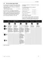
Page 89: ...nd help to protect the environment The pedelec battery motor display screen and charger are recyclable materials You must dispose of and recycle them separately from the domestic waste in compliance with applicable statutory regulations Separate collection and recycling saves reserves of raw materials and ensures that all the regulations for protection of health and the environment are adhered to ...

Page 90: ...1115AD2 134 5 92 mm Brake Tektro HD T275 front and rear Hydraulic disc brake Brake lever n a Brake disc 180 mm front 180 mm rear diameter Rims DDM 2 Hub front FORMULA DC 20FQR 6 BOLT TYPE 14Gx36H Hub rear FORMULA DC 22RQR 6 BOLT TYPE 13Gx36H Tyres Supero Optima Safe 50 622 50 622 Pannier rack SW KM038S SW KM038S Mudguard SKS PET A60 S Shiny Motor BOSCH Performance Line CX BDU450CX Rechargeable bat...

Page 91: ...200 front and rear Hydraulic disc brake Brake lever Shimano BL MT201 front and rear n a Brake disc 180 mm front 160 mm rear Rims Taurus 2000 Hub front Shimano HB M600QR Hub rear Shimano FH M6000QR Tyres Schwalbe Marathon Plus 50 622 Pannier rack Standwell SW KM038S SW KM038S Mudguard SKS PET A60 S Matt Motor BOSCH Performance Line CX BDU450CX Rechargeable battery BOSCH PowerTube 625 W Display BOSC...

Page 92: ...et missing New bell as specified in the parts list Suspension elements Fork suspension fork Check for damage O K Damage detected New fork as specified in the parts list Rear frame damper Check for damage O K Damage detected New fork as specified in the parts list Suspension seat post Check for damage O K Damage detected New fork as specified in the parts list Brake system Brake lever Check mount f...

Page 93: ...lling 10 too fast slow Take pedelec out of service until the source of the error is found Cabling Visual inspection O K Failure in system damage kinked cables New cabling Battery mount Firmly in position lock contacts Functional check O K Loose lock doesn t close no contacts New battery mount Motor Visual inspection and mount O K Damage loose Refasten motor contact motor manufacturer new motor Sof...

Page 94: ...se Retighten screws Attachments 6 months Check mount fastening O K Loose Retighten screws Bell 6 months Functional check O K No ring too quiet missing New bell as specified in the parts list Suspension elements Fork suspension fork To manu facturer s specifica tions Check for damage corrosion fracture Maintenance as specified by manufacturer Lubrication oil change as specified by manufacturer O K ...

Page 95: ...check O K Loose Retighten screws Shift cables 6 months Check for damage Functional check O K Loose or defective Adjust shift cables new shift cables if necessary Front derailleur 6 months Check for damage Functional check O K Gear shift difficult or not possible Adjust Rear derailleur 6 months Check for damage Functional check O K Gear shift difficult or not possible Adjust Electric drive Display ...

Page 96: ...r Readjust gear shift Suspension components fork shock absorber seat post 6 months Functional check O K Suspension too deep or no longer exists Locate defective component and correct Electric drive 6 months Functional check O K Loose connection problems when riding accelerate Locate defective part in electric drive and correct Light system 6 months Functional check O K No continuous light too brig...

Page 97: ...MY21B01 12_1 0_25 06 2020 97 Documents 11 4 Charger operating instructions 0123435678 9 78 7 3951 8 ABC D ABC D ABC ...

Page 98: ...2 15A Output 36V 6A Made in Vietnam Fast Charger BCS250 eBike Battery Charger 36 4 230 0 275 007 907 Li Ion Use ONLY with BOSCH Li Ion batteries Input 230V 50Hz 1 5A Output 36V 4A Made in PRC Robert Bosch GmbH 72757 Reutlingen Germany Standard Charger BCS220 Robert Bosch GmbH 72757 Reutlingen Germany Standard Charger Fast Charger EBE D F A G A C ...

Page 99: ...MY21B01 12_1 0_25 06 2020 99 Documents D Compact Charger A G A C EBE D F ...

Page 100: ...MY21B01 12_1 0_25 06 2020 100 Documents D EBE D F A G A C ...

Page 101: ...MY21B01 12_1 0_25 06 2020 101 Documents D A G A C EBE D F ...

Page 102: ...1 C 0 0 0 C 0 C H G M G N G C 0 G N N G G G C 0 0 G G G M G G G G C C 0 0 C 0 0 C 0 C G N G C 0 0 0 0 0 G G G G G G C C C C C 0 0 0 0 C G M G N C C 0 0 C 0 K G G G N G G L G G G G V S Pk G A CBU G L 0 7 G N G G M G N G N N G A G A G Q N G L A G A N G 0 0 G N G G N G L G G G N G G NN G N G G a N A BG H H BG N BG C N G BG L N G A NN C A G A C EBE D F ...

Page 103: ...J J G N G G G G B G L N G C 0 C G G NN N G G A OG M G L N G 0 C 0 C M M G G G G N G G G G C 0 G C G G NN B G N G G M M G G L P N G N G G G G G G 0 0 0 0 C C C 0 N G M G N G G G OG M G L N G N N A M G G G GM G G N G G G G Q f I i M G G G N G G G PKH N G G OG G M N G L N G N G G M G G G G G G L G G G G 5 H G G G G L N G A G G G L 5 H G G G L G G G G G L OG G G G L M G G G G OG G L M G L N G G N G G ...

Page 104: ... NN 5 H N G G G G M N G G G G N G L M G N G G N G N G M N N G G G G N M G G N G N G G G N D 0 0 0 0 A N C B G G A C H G N G G G G G G H G G G G G G G G G G 5 C C B G G C B G BG A B N G M G N BG G M G G G G G A N B G G K K N G G N M G L G 1 0 0 N G a G G M L G G T N G G M GL BG M G N H N G G G G J C 0 H G K H F F KS O K K Ka L M G G L N L N 0 9 0 A G A C EBE D F ...

Page 105: ...cycle pedelec Source EN 15194 2017 electrically power assisted cycle equipped with pedals and an auxiliary electric motor which cannot be propelled exclusively by means of the auxiliary electric motor except in start up assistance mode Fault Source EN 13306 2018 02 6 1 state of an item 4 2 1 characterized by inability to perform a required function 4 5 1 excluding the inability during preventive m...

Page 106: ... coarse pebble tracks forest trails and other general off road tracks where tree roots and rocks are likely to be encountered Permitted total weight Source EN 15194 2017 weight of the fully assembled pedelec plus the rider and baggage as specified by the manufacturer Quick release device quick release Source EN 15194 2017 lever actuated mechanism that connects retains or secures a wheel or any oth...

Page 107: ...r of manufacture Source ZEG the year of manufacture is the year in which the Pedelec was manufactured The production period is always from August to July of the following year Young adult bicycle Source EN ISO 4210 2 bicycle designed for use on public roads by a young adult whose weight is less than 40 kg with maximum saddle height of 635 mm or more and less than 750 mm see ISO 4210 12 1 Abbreviat...

Page 108: ...ycle 21 17 1064 BULLS Cross Mover Evo 2 26 Wave City and trekking bicycle Year of manufacture 2020 and year of manufacture 2021 complies with the following applicable EU provisions Machinery Directive 2006 42 EC Directive 2011 65 EU RoHS Electromagnetic Compatibility Directive 2014 30 EU The safety objectives in the Low Voltage Directive 2014 35 EU have been met in compliance with Appendix I No 1 ...

Page 109: ...MY21B01 12_1 0_25 06 2020 109 Appendix II Declaration of conformity for incomplete machine ...

Page 110: ...MY21B01 12_1 0_25 06 2020 110 Appendix ...

Page 111: ...MY21B01 12_1 0_25 06 2020 111 Appendix ...
Page 112: ...ing force Checking the quick releases 41 Setting the quick releases 41 Control panel 20 31 D Direction of travel 17 Display battery 20 Display 17 20 attaching 64 charging the battery 64 cleaning 73 removing 64 Position 31 Drive system 17 switching off 63 switching on 63 E Electric gear shift 17 Electrical cable check 77 Emergency stop system 12 F Fork care 74 setting the compression damper 69 Fram...

Page 113: ...tton 31 Riding light 20 32 checking function 57 Rim 15 check 75 checking 75 S Saddle 14 changing the saddle tilt 51 changing the seat length 52 determining the saddle height 51 52 Seat post 14 Securing hook 19 Shifter 31 checking 77 setting 82 Spoke 15 Stem care 74 check 45 77 cleaning 72 Suspension fork cleaning 71 System message 35 48 System setting 34 changeable 33 34 35 66 System data 34 T Tac...

Reviews: