MY21B01 - 12_1.0_25.06.2020
53
Operation
6.5.2
Adjusting the handlebars
6.5.3
Adjusting the stem
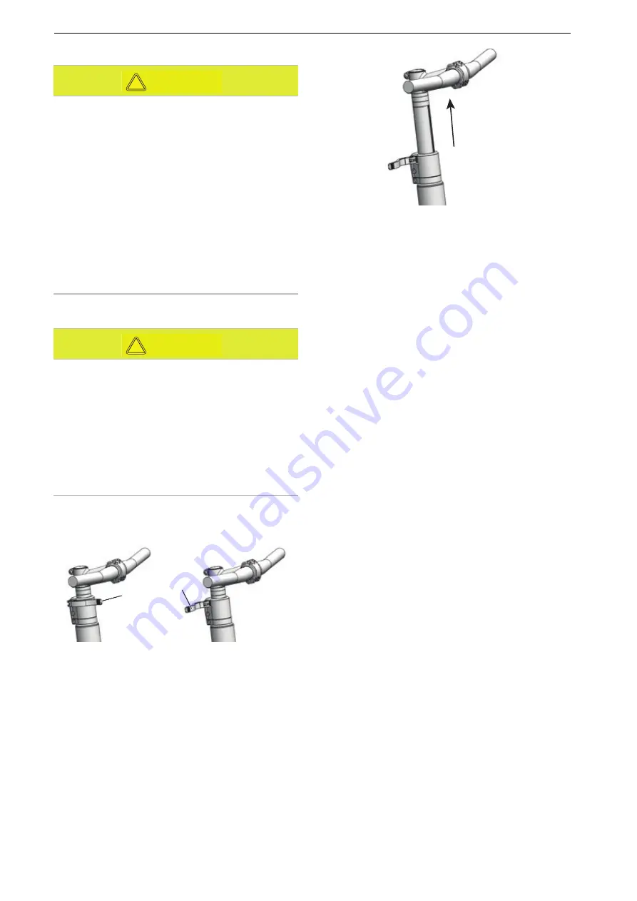
6.5.3.1 Adjusting the height of the handlebars
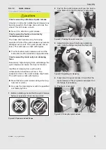
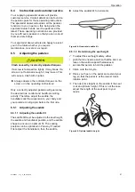
1
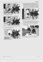
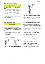
Open the stem clamping lever.
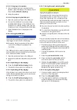
Figure 53: Open (2) and closed (1) stem clamping lever; All
Up used as an example
Figure 54: Pulling the locking lever upwards; All Up used
as an example
2
Pull out the handlebars to the required height.
Observe minimum insertion depth.
3
Close the stem clamping lever.
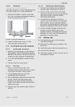
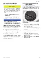
6.5.3.2 Adjusting the quick release clamping
force
If the
handlebar clamping lever
stops before
reaching its end position, unscrew the
knurled
nut
.
Tighten the
knurled nut
on the seat post if the
seat post clamping lever's
clamping force is not
effective enough.
If you are unable to set the clamping force, the
specialist dealer will need to check the quick
release.
6.5.4
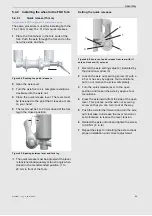
Retracting the brake linings
Disc brakes require wearing-in time. The braking
force increases over time. You therefore need to be
aware that the braking force may increase during the
wearing-in period. The same happens after brake
pads or discs are replaced.
1
Accelerate pedelec to about 25 km/h.
2
Brake pedelec until it comes to a halt.
3
Repeat process 30–50 times.
The disc brake is retracted and provides
optimal braking power.
Crash caused by incorrectly set clamping
force
Excessively high clamping force will damage the
quick release and cause it to lose its function.
Insufficient clamping force will result in
unfavourable transmission of force. This can
cause components to break. This will cause a
crash with injuries.
Never fasten a quick release using a tool (e.g.
hammer or pliers).
Only use the clamping lever with the specified
set clamping force.
Crash caused by loose stem
Incorrectly fastened screws may come loose due
to impact. The stem may no longer be firmly fixed
in its position as a result. This will cause a crash
with injuries.
Check the handlebars and the quick release
system are firmly in position after the first two
hours of riding.
CAUTION
!
CAUTION
!
1
2
Summary of Contents for 21-15-1016
Page 99: ...MY21B01 12_1 0_25 06 2020 99 Documents D Compact Charger A G A C EBE D F ...
Page 100: ...MY21B01 12_1 0_25 06 2020 100 Documents D EBE D F A G A C ...
Page 101: ...MY21B01 12_1 0_25 06 2020 101 Documents D A G A C EBE D F ...
Page 109: ...MY21B01 12_1 0_25 06 2020 109 Appendix II Declaration of conformity for incomplete machine ...
Page 110: ...MY21B01 12_1 0_25 06 2020 110 Appendix ...

