Page 29
TR
M2
J1
J2
J3
J4
J5
J6
J7
TR
M1
TR
M2
J1
J2
J3
J4
J5
J6
J7
TR
M1
CAUTION
DISC
AR
D D
EC
AN
TER
IF:
. C
RA
CK
ED
. S
CR
AT
CH
ED
. B
OI
LE
D D
RY
. H
EA
TE
D W
HE
N E
MP
TY
. U
SE
D O
N H
IG
H
FL
AM
E
. O
R
EX
PO
SE
D
ELE
CTR
IC
E
LE
ME
NT
S
FA
ILUR
E TO C
OM
PLY
R
ISK
S IN
JUR
Y
PN
: 65
8
19
85
B
UNN
-O
-M
AT
IC
C
OR
PO
RA
TIO
N
FUN
NEL C
ON
TEN
TS
A
RE HO
T
!
CAUTION :
W
AR
M
ER
S
AN
D S
UR
FA
CE
S A
RE
H
OT
ON
/LOW
ER
START
FRO
NT-S
IDE-R
EAR
CAUTION :
W
AR
M
ER
S A
ND
S
UR
FA
CE
S
AR
E
HO
T
ON
/LOW
ER
STA
RT
FRO
NT-SIDE
-R
EAR
LIMIT THERMOSTAT
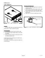
Location:
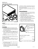
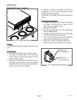
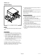
The limit thermostats are located inside the front
access panel on the front side of the tanks.
Test Procedures:
1. Disconnect the brewer from the power source.
2. Disconnect the blue and black wires from the limit
thermostat.
3. With an ohmmeter, check for continuity across the
limit thermostat terminals.
If continuity is present as described, the limit thermo-
stat is operating properly.
If continuity is not present as described, replace the
limit thermostat.
P1800
P1878
SERVICE (cont.)
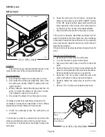
BLU from Control
Board
BLK from Terminal
Block
FIG. 11 LIMIT THERMOSTATS
Removal and Replacement:
1. Remove the black and blue wires from limit ther-
mostat terminals.
2. Carefully slide the limit thermostat out from under
the retaining clip and remove limit thermostat.
3. Carefully slide the new limit thermostat into the
retaining clip.
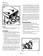
4. Refer to FIG. 12 when reconnecting the wires.
FIG. 12 LIMIT THERMOSTAT WIRING
29319 091203


