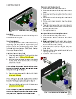
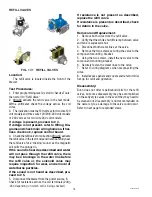
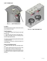
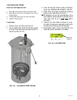
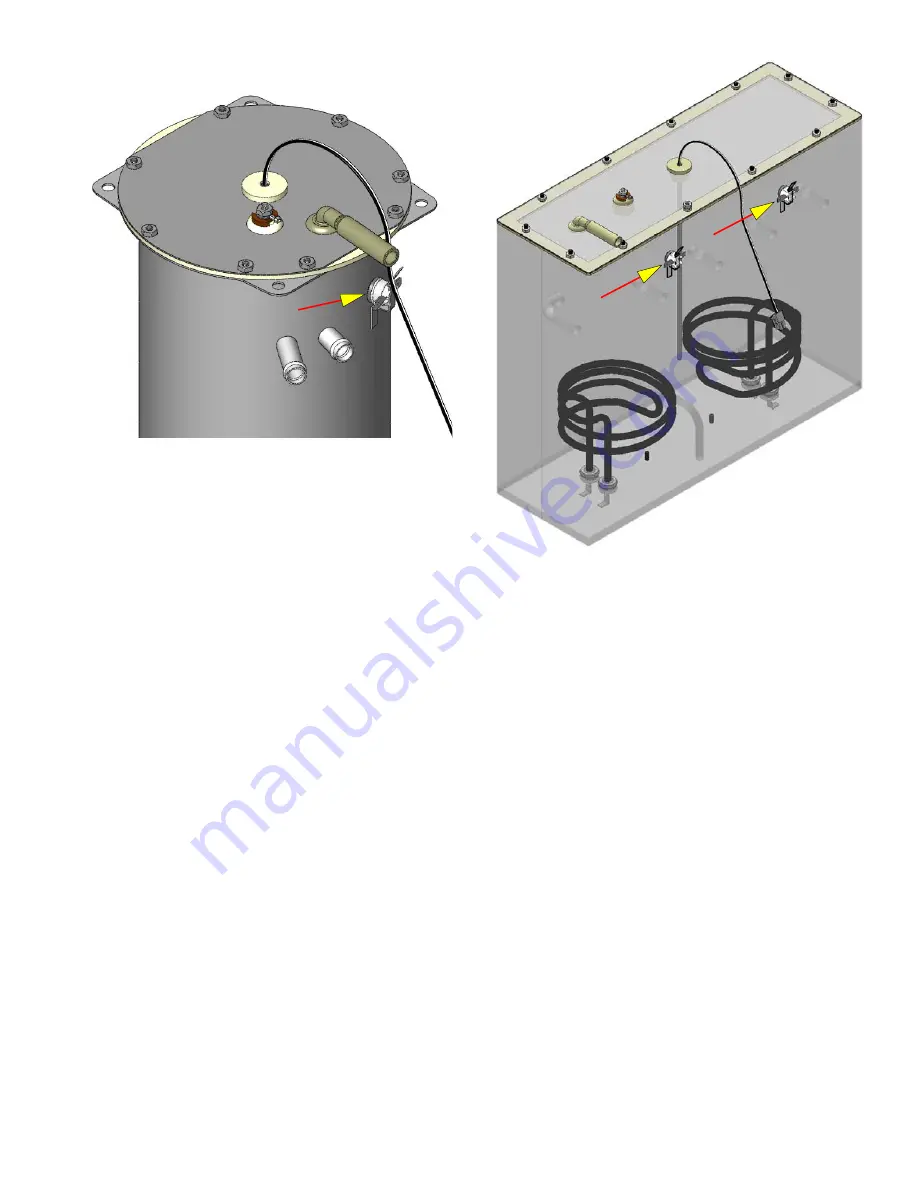
background image

21

LIMIT THERMOSTAT

Location:

The limit thermostat is located on the tank lid (on the 
front of the tank on twins).
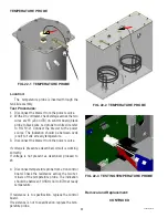
Test Procedures:

1.  Disconnect the brewer from the power source and 
allow to cool.
2.  Disconnect the wires from the limit thermostat.
3.  With an ohmmeter, check for continuity across 
the limit thermostat terminals.

If continuity is present as described, the limit thermostat 
is operating properly.
If continuity is not present as described, replace the 
limit thermostat.

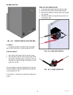
Removal and Replacement:

1.  Remove the wires from limit thermostat termi-
nals.
2.  Carefully slide the limit thermostat out from under 
the retaining clip and remove limit thermostat.
3.  Carefully slide the new limit thermostat into the 
retaining clip. Ensure the metal face has good contact 
with tank.


FIG. 21-1  LIMIT THERMOSTAT

FIG. 21-2  LIMIT THERMOSTATS

42461 081310

Summary of Contents for ICB

Page 1: ...EPAIR MANUAL BUNN O MATIC CORPORATION POST OFFICE BOX 3227 SPRINGFIELD ILLINOIS 62708 3227 PHONE 217 529 6601 FAX 217 529 6644 42461 0000B 08 11 2010 Bunn O Matic Corporation ITB ITCB HV ICB TWIN Infusion Series ...

Page 2: ... sole discretion that the equipment does not conform to the warranty BUNN at its exclusive option while the equipment is under warranty shall either 1 provide at no charge replacement parts and or labor during the applicable parts and labor warranty periods specified above to repair the defective components provided that this repair is done by a BUNN Authorized Service Representative or 2 shall re...

Page 3: ...ter faucet for allied beverage use It is only for indoor use on a sturdy counter or shelf CONTENTS Warranty 2 Contents 3 Troubleshooting 4 Diagnostic Displays 9 Access 10 Control Board 11 Membrane Switch 12 Brew Valves Early 13 Brew Valves Current 14 Refill Valves 15 Tank Heaters 17 Limit Thermostat 18 Temperature Probe 19 DV Selector Switch 21 On Off Switch 22 Schematic Wiring Diagrams 23 42461 0...

Page 4: ...l connections tight and isolated This brewer is heated at all times Keep away from combustibles WARNING Exercise extreme caution when servicing electrical equipment Unplug the brewer when servicing except when electrical tests are specified Follow recommended service procedures Replace all protective shields or safety notices Before troubleshooting this brewer check for the following Control Board...

Page 5: ... control board 1 Refill valve Press ENABLE BREW switch on control panel to determine if power is ON Make sure water is ON Brewer has shut down due to mal function See Diagnostic Section in this manual Make sure ON OFF Switch is ON and indicator is lit Remove the Level Probe s and check for lime deposit on tip Clean and reinstall Check valve Remove Level Probe and check for lime deposits on tip Cle...

Page 6: ...uit Heaters will not turn on if water is not grounding level probe Check replace Check replace Check replace Inspect probe and tank assembly for excessive lime deposits Delime as required Check replace Check replace Plumbing lines should not rest on the counter top The brewer must be connected to a cold water supply Remove the tank lid and clean in side of tank with a deliming agent if necessary W...

Page 7: ...justmentsmustbe made with sprayhead installed 2 Lime build up 3 Dispense Valve Brewer has shut down due to mal function See Diagnostics Waterlinesandvalvestothebrewer must be open Check for voltage across the termi nals at the terminal block The indicator lamp must be lit Allow brewer to heat until ready or disable the brew lockout feature Water must be in contact with refill probe before brew cyc...

Page 8: ...ce an empty brew funnel on an empty decanter beneath the spray head Initiate brew cycle and check the water temperature immediately below the sprayhead with a ther mometer The reading must not be less than 195 F 91 C Adjust the temperature setting to increase the water temperature Refer to Initial Set up instructions BUNN paper filters must be used for proper extraction A fine drip or grind must b...

Page 9: ...ly line too small or ob structed 3 Inlet Solenoid failure 4 Control Board Failure 5 ON OFF switch is OFF 1 Temperature Sensor Probe open 1 Temperature Sensor Probe wire s shorted A Wait for the brewer to heat to the proper temperature B Disable the BREW LOCKOUT function Refer to programming section for procedure Replace or repair as needed Replace or repair as needed Check water supply shut off Re...

Page 10: ...e unplugged when servicing except when electrical tests are re quired and the test procedure specifically states to plug in the brewer WARNING Disconnect the brewer from the power source before the removal of any panel or the replace ment of any component All components are accessible by the removal of the top cover front access panel ICB or rear access panel ITCB ITB Refer to wiring diagrams at t...

Page 11: ...4 4 to J14 5 ITB only If no voltage is present replace the trans former If voltage is present and brewer does not power on replace the control board FIG 11 1 CONTROL BOARD Removal and Replacement 1 Disconnect brewer from power source 2 Disconnect the wires from the relay on the control board 3 Disconnect all of the connectors from the control board 4 Remove the two nuts securing the control board ...

Page 12: ...R2 Left Funnel Lock TH2 MOV1 Refill solenoid TH3 MOV3 BR3 Right Funnel Lock TH4B MOV2 Tank Heaters TH5 MOV5 Left Brew Solenoid TH6 MOV7 Right Brew Solenoid TH7 MOV8 Left Bypass Solenoid TH8 MOV6 Right Bypass Solenoid Connector J17 13 J17 14 J17 5 J17 6 J17 7 Relay Terminal J17 3 J17 2 J17 1 J17 10 42461 081310 ...

Page 13: ...TRIAC MAP Triac Load Component TH2 MOV1 BR2 Optional Funnel Lock ICB TH4B MOV2 Refill solenoid TH6 MOV4 Brew Solenoid TH7 MOV3 Tank Heater s TH9 MOV5 Dilution or Bypass Solenoid Connector J17 13 J17 14 J17 5 J17 3 Relay Terminal J17 1 42461 081310 ...

Page 14: ...4 1 TRIAC MAP Triac Load Component TH1 MOV3 Main or Left Dilution TH2 MOV1 Refill solenoid TH3 MOV2 Brew Solenoid TH4 MOV4 Right Dilution TH6 MOV6 Sweetner TH7 MOV7 Tank Heater Connector J10 1 J10 2 J10 3 J10 4 J10 5 TR1 TR6 42461 081310 ...

Page 15: ...cebefore disconnecting ribbon cable from control board Removal and Replacement 1 Disconnect the ribbon cable from the 22 pin con nector on the control board 2 Gently peel the membrane switch from the front face plate assembly 4 Remove any adhesive that remains on the front face plate 5 Remove the adhesive backing from the new mem brane switch Insert the ribbon cable through the slot in the front f...

Page 16: ...rity of meter leadsarereversed readingwillindicate 150 160VDC Double these readings for 240 volt coils If voltage is present as described but no coil action is observed brew valve is defective Replace valve and test again to verify repair If voltage is not present as described refer to Wir ing Diagrams and check the brewer wiring harness Also check the control board and switch for proper operation...

Page 17: ...If the polarity of meter leadsarereversed readingwillindicate 150 160VDC Double these readings for 240 volt coils If voltage is present as described but no coil action is observed valve is defective Replace valve and test again to verify repair If voltage is not present as described refer to Wiring Diagrams and check the brewer wiring harness Also check the control board and membrane switch for pr...

Page 18: ...cles If the sound is not heard as described pro ceed to 5 5 Disconnectthebrewerfromthepowersource 6 Check for resistance across the coil terminals 200 2k depending on which coil is being checked If resistance is not present as described replace the refill valve If resistance is present as described check for debris in the valve Removal and Replacement 1 Remove both wires from the refill valve 2 Ve...

Page 19: ...19 REFILL VALVES EARLY ICB CURRENT ICB ITB EARLY ITCB CURRENT ITCB ITB DD SCREEN STRAINER SCREEN STRAINER Flow control used on dual dilution models only 42461 081310 ...

Page 20: ...EATERS 1425W Small Dia 2268W Large Dia 1425W 120V 9 5 11 0 3500W 240V 15 1 17 6 1680W 120V 7 9 9 2 1800W 120V 7 4 8 7 2268W 120V 5 9 6 9 3000W 208V 12 9 15 1 3000W 240V 17 9 20 7 3500W 200V 10 5 12 2 TERMINAL TO SHEATH INFINITE OPEN HEATER RESISTANCE NOTE If any resistance is read between sheath and either terminal remove and inspect heater for cracks in the sheath Removal and Replacement 1 Remove...

Page 21: ...rminals Ifcontinuityispresentasdescribed thelimitthermostat is operating properly If continuity is not present as described replace the limit thermostat Removal and Replacement 1 Remove the wires from limit thermostat termi nals 2 Carefully slide the limit thermostat out from under the retaining clip and remove limit thermostat 3 Carefully slide the new limit thermostat into the retaining clip Ens...

Page 22: ...brewer from the power source If voltage is present as described circuit is working correctly If voltage is not present as described proceed to 4 4 Disconnect temperature probe from J9 on control board Check the resistance across the two ter minals of the temperature probe The indication should be between 10 5K cool to 870 at ready temperature If resistance is to specification replace the control b...

Page 23: ...EMP PROBE DONE 200 CAL 200 FIG 23 2 CALIBRATION Adjust this number 3 Press and hold the Hidden button until display reads CAL TEMPERATURE SENSOR NO YES 4 Select YES The display should show something similar to the screen below FIG 20 2 NOTE Variables such as tank set temperature could show different numbers than the example shown here Tank must be at it s ready temp before calibrating 5 Press the ...

Page 24: ...120 208 240V position check for continuity between the two left terminals If continuity is not present as described replace the switch Removal and Replacement 1 Disconnect the brewer from the power source 2 Disconnect the three wires from the selector switch 3 Remove the switch mounting nut from the under side of component mounting bracket remove switch from bracket 4 Installnewswitchincomponentmo...

Page 25: ...ower terminals on each side of the switch There should be continuity between the two left ter minals and between the two right terminals when ON no continuity when OFF If continuity is not present as described replace the switch Removal and Replacement 1 Disconnect the brewer from the power source 2 Disconnect the wires from the power switch 3 Remove the switch mounting screws from the left side o...

Page 26: ... WIRE 120 208V AC 3 WIRE 120 240V AC 3 WIRE SINGLE PHASE BLK BLK RED WHI GRN CONTROL PANEL ASSY J2 1 1 22 J2 5 J2 15 J2 20 J2 22 J2 10 PROG L BREW A PROG R BREW C STATIC SHIELD J3 1 J3 8 J3 5 BLK PNK WHI GRN LEVEL PROBE t WHI 14 WHI VIO 14 BLU 14 RED 14 TANK HEATER 1680W TANK HEATER 1800W SELECTOR SWITCH J13 1 DILUTION SOL SOL SOL TRANSFORMER 10VA J16 1 J16 5 J18 1 J9 1 J9 7 1 3 FULL FULL HALF HAL...

Page 27: ...N WHI GRN WHI BLU RED WHI BLU FUNNEL SENSOR 200V AC 2 WIRE 230V AC 2 WIRE SINGLE PHASE BLK BLK RED WHI GRN CONTROL PANEL ASSY J2 1 1 22 J2 5 J2 15 J2 20 J2 22 J2 10 PROG L BREW A PROG R BREW C STATIC SHIELD J3 1 J3 8 J3 5 BLK PNK WHI GRN LEVEL PROBE t RED 14 RED 14 TANK HEATER 3500W J13 1 DILUTION SOL SOL SOL TRANSFORMER 10VA J16 1 J16 5 J18 1 J9 1 J9 7 1 3 FULL FULL HALF HALF ON OFF ON OFF BREW B...

Page 28: ...R 120V AC 2 WIRE 120 208V AC 3 WIRE 120 240V AC 3 WIRE SINGLE PHASE BLK BLK RED WHI GRN CONTROL PANEL ASSY J2 1 1 22 J2 5 J2 15 J2 20 J2 22 J2 10 PROG L BREW A PROG R BREW C STATIC SHIELD J3 1 J3 8 J3 5 BLK PNK WHI GRN LEVEL PROBE t WHI 14 WHI VIO 14 BLU 14 RED 14 TANK HEATER 1680W TANK HEATER 1800W SELECTOR SWITCH J13 1 DILUTION SOL SOL SOL TRANSFORMER 10VA J16 1 J16 5 J18 1 J9 1 J9 7 1 3 FULL FU...

Page 29: ...208V AC 3 WIRE 120 240V AC 3 WIRE SINGLE PHASE BLK CONTROL PANEL ASSY J2 1 1 22 J2 5 J2 15 J2 20 J2 22 J2 10 PROG L BREW A PROG R BREW C STATIC SHIELD J3 1 J3 8 J3 5 BLK PNK WHI GRN LEVEL PROBE t WHI 14 WHI VIO 14 BLU 14 RED 14 TANK HEATER 1680W TANK HEATER 1800W SELECTOR SWITCH J13 1 DILUTION SOL SOL SOL TRANSFORMER 10VA J16 1 J16 5 J18 1 J9 1 J9 7 1 3 FULL FULL HALF HALF ON OFF ON OFF BREW B BLK...

Page 30: ...AC 3 WIRE 120 240V AC 3 WIRE SINGLE PHASE BLK BLK RED WHI GRN CONTROL PANEL ASSY J2 1 1 22 J2 5 J2 15 J2 20 J2 22 J2 10 PROG L BREW A PROG R BREW C STATIC SHIELD J3 1 J3 8 J3 5 BLK PNK WHI GRN LEVEL PROBE t WHI 14 WHI VIO 14 BLU 14 RED 14 TANK HEATER 1680W TANK HEATER 2268W SELECTOR SWITCH J13 1 BYPASS SOL SOL FUNNEL LOCK Optional BRN BLK BRN WHI SOL SOL TRANSFORMER 10VA J16 1 J16 5 J18 1 J9 1 J9 ...

Page 31: ...PROG Digital RIGHT BREW A LEFT PROG RIGHT BREW B STATIC SHIELD J3 1 J3 8 J3 5 BLK PNK WHI GRN LEVEL PROBE t GRY RED 14 TANK HEATER RED 14 TANK HEATER J13 1 LEFT BYPASS SOL SOL LEFT FUNNEL LOCK Optional BRN BLK BRN WHI SOL RIGHT FUNNEL LOCK Optional BLU BLU BLK SOL SOL WHI RIGHT BYPASS SOL WHI ORN LEFT DISPENSE SOL TRANSFORMER 10VA J16 1 J16 5 1 3 WHI VIO J20 1 J20 3 VIO LEFT FUNNEL SENSOR 1 3 LEFT...

Page 32: ... RED WHI BLU FUNNEL SENSOR 200V AC 2 WIRE 230V AC 2 WIRE SINGLE PHASE BLK BLK RED WHI GRN CONTROL PANEL ASSY J2 1 1 22 J2 5 J2 15 J2 20 J2 22 J2 10 PROG L BREW A PROG R BREW C STATIC SHIELD J3 1 J3 8 J3 5 BLK PNK WHI GRN LEVEL PROBE t RED 14 TANK HEATER 3500W J13 1 BYPASS SOL SOL FUNNEL LOCK Optional BRN BLK BRN WHI SOL SOL TRANSFORMER 10VA J16 1 J16 5 J18 1 J9 1 J9 7 1 3 FULL FULL HALF HALF ON OF...

Page 33: ... BREW A LEFT PROG RIGHT BREW B STATIC SHIELD J3 1 J3 8 J3 5 BLK PNK WHI GRN LEVEL PROBE t GRY RED 14 TANK HEATER RED 14 TANK HEATER J13 1 LEFT BYPASS SOL SOL LEFT FUNNEL LOCK Optional BRN BLK BRN WHI SOL RIGHT FUNNEL LOCK Optional BLU BLU BLK SOL SOL RED RIGHT BYPASS SOL RED ORN LEFT DISPENSE SOL TRANSFORMER 10VA J16 1 J16 5 1 3 WHI VIO J20 1 J20 3 VIO LEFT FUNNEL SENSOR 1 3 LEFT FULL LEFT FULL LE...

Page 34: ... FOR DUAL DILUTION MODELS ONLY 3 JUMPER FOR DUAL DILUTION MODELS w SWEETENER ONLY 2 JUMPER FOR SWEETENER MODELS ONLY J15 1 1 22 J15 5 J15 15 J15 20 J15 22 J15 10 PROG L BREW A PROG R BREW C STATIC SHIELD J2 1 J2 8 J2 5 BLK PNK WHI GRN TEMP PROBE LEVEL PROBE t BLK TANK HEATER J3 1 DILUTION MAIN or LEFT SOL SOL SOL WHI RIGHT DILUTION DUAL DILUTION MODELS ONLY SOL TRANSFORMER 10VA FULL FULL HALF HALF...

Page 35: ...I WHI BLU FUNNEL SENSOR 120V AC 2 WIRE 120 208V AC 3 WIRE 120 240V AC 3 WIRE SINGLE PHASE BLK CONTROL PANEL ASSY J2 1 1 J2 5 J2 15 J2 20 J2 22 J2 10 PROG L BREW A PROG R BREW C STATIC SHIELD J3 1 J3 8 J3 5 BLK PNK WHI GRN LEVEL PROBE t WHI 14 WHI VIO 14 BLU 14 RED 14 TANK HEATER 1680W TANK HEATER 2268W SELECTOR SWITCH J13 1 BYPASS SOL SOL SOL BLK COOLING FAN MOT TRANSFORMER 10VA J18 1 J9 1 J9 7 1 ...

Page 36: ...J2 20 J2 22 J2 10 PROG Control PROG Brewer PROG Digital RIGHT BREW A LEFT PROG RIGHT BREW B STATIC SHIELD J3 1 J3 8 J3 5 BLK PNK WHI GRN LEVEL PROBE t GRY RED 14 TANK HEATER RED 14 TANK HEATER J13 1 LEFT BYPASS SOL LEFT DILUTION RELAY RED BLK BLU BLK RIGHT DILUTION RELAY RED BLK SOL WHI RIGHT BYPASS SOL WHI ORN LEFT DISPENSE SOL TRANSFORMER 10VA 1 3 WHI VIO J20 1 J20 3 VIO LEFT FUNNEL SENSOR 1 3 L...

Page 37: ...37 ...

Reviews: