14
SERVICE (CONT.)
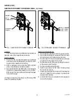
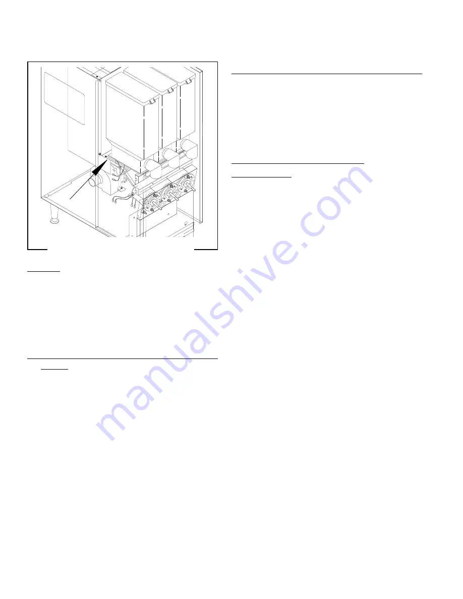
AUGER DRIVE COMPONENTS
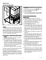
FIG. 4 AUGER DRIVE COMPONENTS
P1341
Location:
The auger components are located inside the bottom
part of the hopper except for the auger drive bracket,
washer and locknut, which are located on the outside
bottom rear of the hopper. The auger motors are located
on the rear of the auger motor mounting panel. Refer
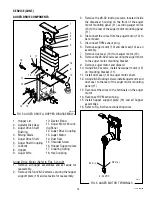
to Fig. 5 for disassembly and assembly.
Test Procedures - Auger Motors without Proximity
Sensor
1. Disconnect the dispenser from the power source.
2. Remove hoppers. Turn elbow up.
3. Back probe check the voltage across the positive
and negative wire with a voltmeter. Connect the
dispenser to the power supply. With the rinse/run
switch in the run position press the appropriate
dispense switch. After a .6 second delay the indica-
tion must be 4.0 to 24.5 volts dc.
4. Disconnect the dispenser from the power supply.
If voltage is present as described and the auger motor
does not rotate, replace the auger motor.
If voltage is not present as described, refer to the wir-
ing diagrams and check the dispenser wiring harness
back to control board. Also verify 24 vac is supplied
to control board from transformer - Refer to Control
Board Testing.
Test Procedures - Auger Motors with Proximity Sensor.
(IMIX only)
1. Open door and flip switch into
PROGRAM
mode.
2. Scroll to
Diagnostics
and select
YES
.
3. Scroll to
Test Augers
.
4. Press the appropriate dispense switch to activate
motor. Refer to
Diagnostics
for further direction.
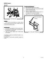
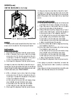
Removal, Cleaning and Replacement:
Hopper & Auger:
1. Open the dispenser door and turn elbow up.
2. Lift the front edge of hopper assy over the tab on
hopper support plate (16) and slide hopper as-
sembly out the front of the dispenser.
3. Remove hopper lid (1) and empty product.
4. Pull off the ejector elbow (10).
5. Remove agitator disk assy (2) by pushing out on
the side of the hopper, rotating the agitator disk
assy out of the mounting hubs and lifting the
agitator disk assy from the hopper. Remove the
mixing blades (4) from the agitator disk by tugging
sharply.
6. Remove auger (9) by pulling it out the front of the
hopper (8).
7. Remove the auger drive bracket by turning it clock-
wise while holding the auger drive shaft firmly.
8. Slide auger drive shaft (5) from auger drive shaft
bushing (3) and remove from hopper (8).
9. Remove locknut (7) from auger drive shaft bush-
ing (3) and remove auger drive shaft bushing from
hopper (8).
10. Wash components in a mild solution of dish deter-
gent using a bristle brush when needed.
11. Rinse and dry each item thoroughly.
12. Check for damaged or broken components, replace
any if necessary and reassemble hopper assem-
bly.
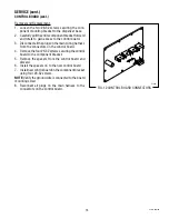
13. Install hopper assy in the dispenser by sliding
hopper assy in the guides on the hopper support
plate (16) until the slot in the bottom rear the hop-
per seats against the shoulder screw (15) in the
hopper support plate.
42032 060109
Summary of Contents for IMIX
Page 10: ...10 42032 060109 NOTES ...
Page 46: ...46 42032 060109 ...
Page 48: ...48 42032 060109 ...


