background image

33

120 VOLTS AC - 2 WIRE 

SINGLE PHASE, 60 HZ

29780.0000A   5/99   ©  1999  BUNN-O-MATIC CORPORATION

M

BLK

RED

WHI/BRN

BLK

VIO

J7

J1          

J6

PNK

C
O
N
T
R
O
L


P
C


B
O
A
R
D

WHI/RED
WHI

GRN
GRN
ORN

ORN

WHI

BLK

WHI/BLK

WHI/GRN

BLU/BLK

BLU/BLK

RED/BLK

RED/BLK

GRY

RED

WHI/ORN

WHI/ORN

J2

WHI

BLK

1

4

1

1

4

1

5

10

J3

BLK

RED

GRN

M

SOL

WHI

WHI

BLK

BLK

BLK

BLK

120V : 24V AC

TRANSFORMER

WHI/BLK

WHI/GRN

1

4

P

R

O

B

E

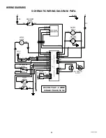
SCHEMATIC WIRING DIAGRAM  PAF

GRN

L1

N

DOOR
LAMP

1

2

RED-22

BLK-22

GRN

GRN

GRN

WHI/RED

WHI/BRN

WHI/RED

WHI/BRN

HOPPER

MOTOR

HOPPER

SWITCH

DOOR

SWITCH

TEST/SERVICE

SWITCH

WHIPPER

MOTOR

MOTOR

SPEED ADJUST

1

3

MAIN POWER

SWITCH

DISPENSE

SOLENOID

TEST

SERVICE

CW

BLK
BLK

BLK

WHI

LOW  PRODUCT

DETECT

WIRING DIAGRAMS

29793 061599

Summary of Contents for POWDER AUTO FILL

Page 1: ...N OPERATING SERVICE MANUAL BUNN O MATIC CORPORATION POST OFFICE BOX 3227 SPRINGFIELD ILLINOIS 62708 3227 PHONE 217 529 6601 FAX 217 529 6644 29793 0000B 1 00 1999 Bunn O Matic Corporation POWDER AUTO FILL ...

Page 2: ...writing to Post Office Box 3227 Springfield Illinois 62708 3227 If requested by Bunn the Buyer shall ship the defective equipment prepaid to an authorized Bunn service location If Bunn determines in its sole discretion that the equipment does not conform to the warranty Bunn shall repair the equipment with no charge for parts during the warranty period and no charge for labor by a Bunn Authorized ...

Page 3: ... the screw into the hinge mount on the Powder Auto Fill cover Repeat for other side 15 Install PAF level probe BOM 29728 1000 by sliding it into the notched area at the top rear of the CDS hopper The probe should be firmly seated in the notch and touching the contact pin protruding from the front of the CDS cooling drum mount NOTE At this point it is important that the CDS machine is fully assembl...

Page 4: ...ill will continue to fill the CDS product hopper until the liquid level in the CDS hopper reaches the product level probe or for 5 minutes which ever occurs first 8 If the Powder Auto Fill fails to fill the CDS hopper in 5 minutes the following will occur a The Powder Auto Fill will stop dispensing prod uct b The door lamp will flash 4 times about every 2 seconds 9 After checking the CDS and Powde...

Page 5: ...ondsforthePowderAuto Fill to initialize observe the door lamp on the whipper panel The door lamp should not be lit If the door lamp is lit consult the fault list and clear the fault before proceeding i Remove the hole plug on the whipper panel Using a screwdriver set potentiometer to approxi mately mid range j Remove the mixing chamber from the Powder Auto Fillandplaceasmallcontainer suchasacup un...

Page 6: ...opper once a week 1 Open the cabinet door 2 Remove the hopper base assembly from the cabi net remove the cover and empty the contents 3 Pull the ejector elbow off the hopper base remove the slide gate from the ejector elbow 4 Removethewiperbladeanddrivegearbyremoving the retaining ring from the wiper blade shaft 5 Remove the auger by pulling it out of the front hopper base 6 Remove the auger drive...

Page 7: ...50 duty cycle Low product level in Powder Auto Fill hopper Two flashes about every 2 seconds CDS Powder Auto Fill probe circuit open Three flashes about every 2 seconds Powder Auto Fill hopper not in place Four flashes about every 2 seconds CDS refill exceeded 5 minutes OFF Door not closed 29793 061599 ...

Page 8: ...olated Keep away from combustibles WARNING Exercise extreme caution when servicing electrical equipment Unplug the dispenser when servicing except when electrical tests are specified Follow recommended service procedures Replace all protective shields or safety notices PROBLEM PROBABLE CAUSE REMEDY CDS and Powder Auto Fill do not run Main power indicator on CDS drawer front OFF Product level in CD...

Page 9: ...1 Refill time exceeded five minutes 1 Improper adjustment of product mix ratio 1 PowderAuto Fillnotconnectedto water source 2 Water source turned off 3 Water line obstructed 1 Check that the Powder Auto Fill is pulled completely forward until the guide rails roll into the indented po sition 2 Position the CDS level probe so that it is located in the notch of the CDS hopper and touching the con tac...

Page 10: ...DS dispenser and for voltage from the CDS dispenser Refer to Service Dispense Solenoid Valve for testing procedures See page 32 Refer to Service Control Board and Probe for testing procedures See page 18 Refer to Service Auger Drive for testing procedures See page 13 Refer to Service Transformer for testing procedures See page 26 A Direction of flow arrow must be pointing towards dispenser B Remov...

Page 11: ...See page 16 Refer to Service Frother for testing procedures See page 15 Refer to Service Dispense Solenoid Valve for testing procedures See page 32 Refer to Service Auger Drive for testing procedures See page 13 Refer to Service Auger Spring for testing procedures See page 13 Refer to Service Auger Motor for testing procedures See page 14 Set the product mix ratio per Adjust ments See page 5 Plumb...

Page 12: ...m the power source before the removal of any panel or the replace ment of any component All components are accessible by opening the door removal of the door panel removal of the dispenser rear panel hopper hopper support plate and top wrap around cover Refer to Fig 1 Contents Auger Drive Components 13 Auger Motor 14 Frother and Mixing Whipper Chamber 15 Whipper Motor 16 Control Board and Level Pr...

Page 13: ...acket 7 off of the auger drive shaft 13 10 Remove auger drive shaft 13 from hopper base 9 11 Washcomponentsinamildsolutionofdishdeter gent using a bristle brush when needed AUGER DRIVE COMPONENTS P1922 12 Rinse and dry each item thoroughly 13 Check for damaged or broken components re place any if necessary and reassemble hopper assembly 14 Installhopperassemblyinthedispenserbysliding hopperassy on...

Page 14: ...ve six 8 32 screws securing the rear cover and remove the rear cover 3 Remove the four 8 32 screws located inside the dispenser housing on the lower right front of the auger motor mounting panel securing the auger motor mounting bracket and auger motor to the rear of the auger motor mounting panel 4 Disconnect the wires from the auger drive motor 5 Remove the auger motor mounting bracket auger mot...

Page 15: ...a mild solution of dish deter gent using a bristle brush 9 Rinse thoroughly and allow to dry before reinstall ing in the dispenser 10 Slide whipper chamber receptacle with seal 6 and O ring 4 on to the motor shaft 11 Rotate the receptacle with seal 6 counterclock wiseuntilitsnapsintoplaceonthemotormounting nuts 7 12 Push frother 5 onto the motor shaft making sure the flat in the frother 5 lines up...

Page 16: ...nser 3 Removethefour 8 32screwssecuringthehopper support panel to the auger motor mounting panel and the whipper motor mounting panel 4 Slowly lift the hopper support panel up and discon nect the red black and green wires from the hopper switch 5 Pull the mixing chamber out of the whipper cham ber 6 Twist the whipper chamber clockwise and pull it off the whipper chamber receptacle 7 Pull the froth...

Page 17: ...nel using the four 8 32 screws 20 Install whipper chamber on the whipper chamber receptacle by twisting counterclockwise until tabs on the whipper chamber lock with the tabs on the whipperchamberreceptacle Besuredispenseport is pointing down WHIPPER MOTOR cont FIG 9 WHIPPER MOTOR TERMINALS P1903 FIG 10 HOPPER SWITCH TERMINALS P1904 21 Install dispense tip into the bottom of the whipper chamber 22 ...

Page 18: ...r pin connector to the control board J7 10 Disconnect the twelve pin connector J1 from the control board 11 Measure the resistance between pins 8 12 of the twelve pin connector on the wiring harness using an ohmmeter The indication must be between 298k ohms and 304k ohms If the resistance measures as described proceed to 12 If the resistance does not measure as described refer to the wiring diagra...

Page 19: ...t the OFF posi tion on the main power switch If voltage is present as described proceed to 12 If voltage is not present as described replace the photo transistor 12 Check the voltage across pins 1 positive 3 negative of the four pin connector on the control board with a voltmeter Remove the hopper from the dispenser connect the dispenser to the power source and select the ON position of the main p...

Page 20: ...rd 3 Remove the four 6 32 keps nuts securing the control board to the hopper motor mounting panel 4 Remove the control board 5 Removethefourspacersfromtheoldcontrolboard and install them into the new control board 6 Instal the new control board using the four 6 32 keps nuts 7 Reconnect the two plugs J1 and J7 from the main wiring harness the potentiometer plug J3 the photo transistor plug J6 and t...

Page 21: ...d Replacement 1 Disconnect the dispenser from the power source 2 Open the dispenser door and remove the hopper assembly out the front of the dispenser 3 Removethefour 8 32screwssecuringthehopper support panel to the auger motor mounting panel and the whipper motor mounting panel 4 Slowly lift the hopper support panel up and discon nect the red black and green wires from the hopper switch 5 Remove ...

Page 22: ... Disconnect the dispenser from the power source 2 Open the dispenser door and remove the hopper assembly out the front of the dispenser 3 Removethefour 8 32screwssecuringthehopper support panel to the auger motor mounting panel and the whipper motor mounting panel 4 Slowly lift the hopper support panel up and discon nect the red black and green wires from the hopper switch 5 Removetheswitchmountin...

Page 23: ... Openthedispenserdoorandremovethefivescrews securing the rear cover to the door 3 Disconnect the lamp cord assembly from the lamp holder socket assembly and set the rear panel aside 4 Cut the terminals off of the lamp cord assembly 5 Removelampcordassemblyfromthedoorassem bly and discard 6 Push new lamp cord wires through the holes on the top of the door assembly 7 Strip the wires from the new lam...

Page 24: ...ECTOR P1923 Location The lamp cord connector is located on top of the dispenser Test Procedures 1 Disconnect the dispenser from the power source 2 Disconnect the lamp cord from the lamp cord connector 3 Disconnect the plug on the dispenser main harness from the connector from the lamp cord connector 4 Check the voltage across the two pin holes on the main harness plug with a voltmeter and Day Nigh...

Page 25: ...g in the lamp cord assembly to the lamp cord connector assembly on top of the dispenser 14 Refer to Fig 22 when reconnecting the wires FIG 22 LAMP HOLDER SOCKET ASSEMBLY WIRES P1929 LAMP HOLDER SOCKET ASSEMBLY FIG 21 LAMP HOLDER SOCKET ASSEMBLY P1927 Location The lamp holder socket assembly is located inside the dispenser door Test Procedures 1 Disconnect the lamp cord from the lamp cord connector...

Page 26: ...nnector at the control board Connect the dispenser to the power source The indication must be 24 volts ac If voltage is present as described the transformer is operating properly If voltage is not present as described replace the transformer Removal and Replacement 1 Remove the hopper from the dispenser 2 Removethefour 8 32screwssecuringthehopper support panel to the dispenser 3 Disconnect the red...

Page 27: ...es not measure as described replace the potentiometer assembly 7 Adjust the potentiometer fully counterclockwise 8 Check resistance between pins 1 2 of the poten tiometer connector with an ohmmeter The indica tion must be between 800 and 1200 ohms Check theresistancebetweenpins2 3ofthepotentiom eter connector with an ohmmeter The indication must be less than 20 ohms Iftheresistancemeasuresasdescri...

Page 28: ... round head screws securing the front of the housing to the side panels 8 Remove the six 8 32 truss head screws securing the back of the housing to the side panels 9 Carefully lift and spread the housing to remove it from the rest of the dispenser 10 Disconnect the photo transistor J6 or LED J2 plug from the control board 11 Cut the cable tie securing the cable assembly to the cable tie mount 12 G...

Page 29: ...ntheN O andCOM termi nals of the hopper switch using an ohmmeter Continuity must be present when the actuator is engaged Continuity must not be present when actuator is released If continuity is present as described refer to wiring diagram and check the dispenser wiring harness If continuity is not present as described replace the hopper switch Removal and Replacement 1 Disconnect the dispenser fr...

Page 30: ...k surface 4 Disconnect the door lamp cord from the lamp connector 5 Remove the two 8 32 screws securing the door hinge to the dispenser housing 6 Carefully pull the door forward until the door sup port arms come completely out of the dispenser housing and set aside 7 Remove the six 8 32 truss head screws securing the rear cover to the dispenser housing 8 Remove the six 8 32 round head screws secur...

Page 31: ... 5 Remove the bulkhead fitting from the inlet to the pressure regulator 6 Remove the pressure regulator assembly 7 Attach the regulator to the bulkhead fitting making sure that the copper bushing is seated properly in the regulator and tighten securely 8 Tighten the nut securing the bulkhead fitting to the dispenser housing 9 Attach the 25 copper tube to the regulator assem bly and tighten securel...

Page 32: ...ound as the magnet attracts 7 Disconnect the dispenser from the power source If the sound is heard as described and water will not pass through the solenoid valve there may be a block age in the water line before the solenoid valve or the solenoid valve may require inspection for wear and the removal of waterborne particles If the sound is not heard as described replace the solenoid valve Removal ...

Page 33: ... WHI ORN J2 WHI BLK 1 4 1 1 4 1 5 10 J3 BLK RED GRN M SOL WHI WHI BLK BLK BLK BLK 120V 24V AC TRANSFORMER WHI BLK WHI GRN 1 4 P R O B E SCHEMATIC WIRING DIAGRAM PAF GRN L1 N DOOR LAMP 1 2 RED 22 BLK 22 GRN GRN GRN WHI RED WHI BRN WHI RED WHI BRN HOPPER MOTOR HOPPER SWITCH DOOR SWITCH TEST SERVICE SWITCH WHIPPER MOTOR MOTOR SPEED ADJUST 1 3 MAIN POWER SWITCH DISPENSE SOLENOID TEST SERVICE CW BLK BL...

Page 34: ... BLK RED BLK GRY RED WHI ORN WHI ORN J2 WHI BLK 1 4 1 1 4 1 5 10 J3 BLK RED GRN M SOL WHI WHI BLK BLK BLK BLK 230V 24V AC TRANSFORMER WHI BLK WHI GRN 1 4 P R O B E SCHEMATIC WIRING DIAGRAM PAFA GRN YEL L1 L2 DOOR LAMP 1 2 RED 22 BLK 22 GRN GRN GRN WHI RED WHI BRN HOPPER MOTOR HOPPER SWITCH DOOR SWITCH TEST SERVICE SWITCH WHIPPER MOTOR MOTOR SPEED ADJUST 1 3 MAIN POWER SWITCH DISPENSE SOLENOID TEST...

Reviews: