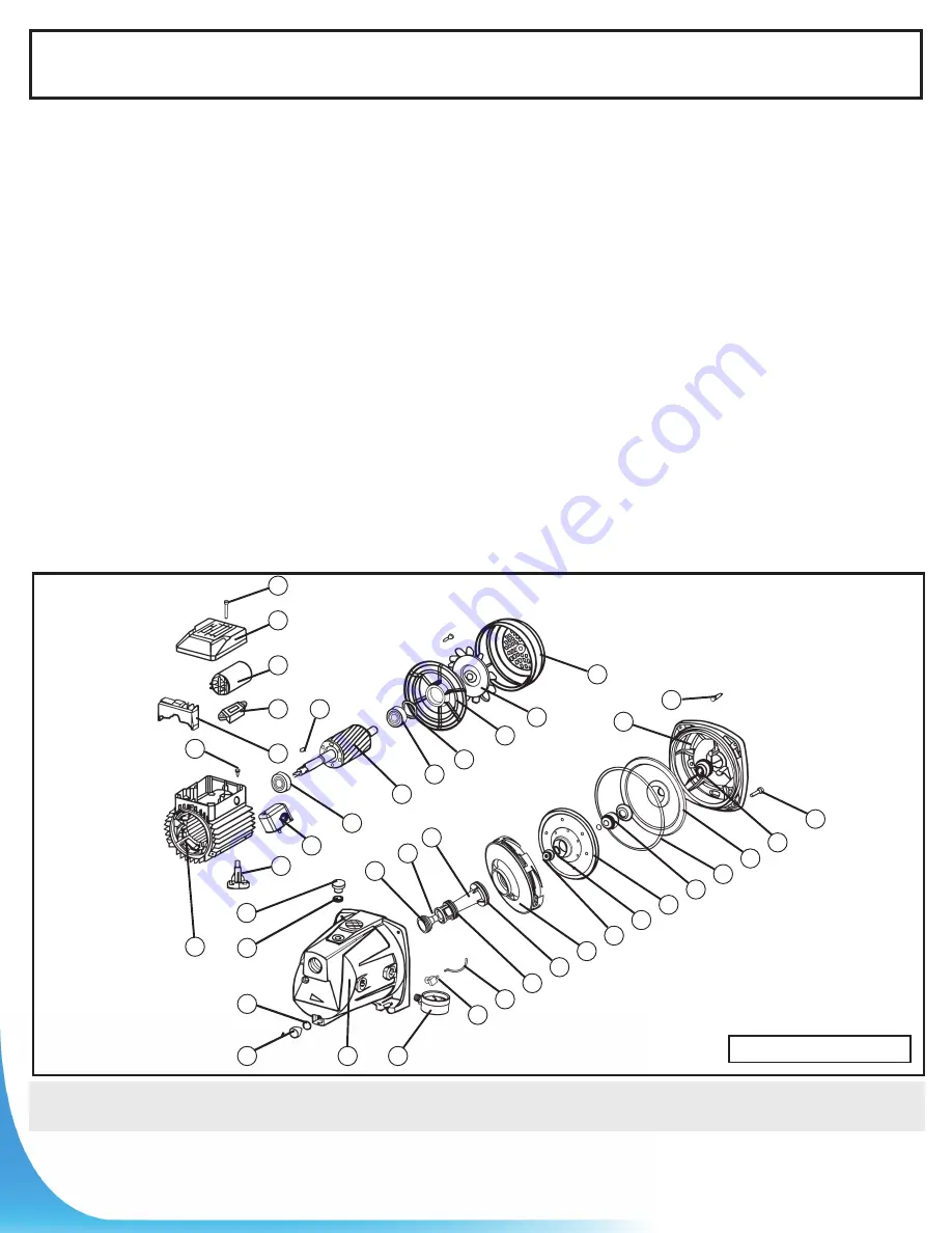
background image

9

REPAIR PARTS

Repair parts may be ordered from your authorized point of sale or from

BUR-CAM PUMPS

Ref P

art        

Description

1

506391

C.I. pump body

2

750769

Pressure gauge

3

52319

1/4”NPT 1/8”barb brass adaptor

4

506052

Nozzle “O” ring

5

750748

Plastic tubing

6

506389

Nozzle

7  506380

Venturi

8  506388

Venturi “O” ring

9

506053S

Venuri “O” ring

10 506085

Diffuser

11  506055

Impeller brass nut

12 506381

Gasket

13 506083

Noryl impeller

14  506057

Mechanical shaft seal

15  350129

Pump body “O” ring

16  506059GP

S.S. seal plate

17  506060

Sand slinger     

18  506062

Body cap screw

19 506061GP

Pump bracket 

20 506383

Motor flange cap screw

21  506074GP

Fan cover

Ref P

art        

Description

22 506073W

Motor fan

23 506072GP

Motor end bell

24 506385

Wave spring washer

25 350335

Motor bearing fan side 

26 506070GP

Rotor/shaft 

27 506069

Rotor shaft key 

28 350335

Motor bearing pump side

29 750957S

Pressure switch

30  506075

Motor/pump foot   

31  506300

Priming  plug 

32 506400

Priming plug washers 

33  506315

Washer

34 506299

Draining plug

35 506067GP2V Stator winding 

36 506386

Grounding screw

37  506065

Capacitor junction block 

38 506094

115/230V selector

39 506064

Motor capacitor    

40 506014

Cover box junction 

41 506384

Cover box screw

506121SW      2009

40

41

39

37

30

29

38

1

5

3

2

31

32

33

34

35

36

15

14

10

9

6

4

17

7

16

18

8

19

22

23

25

26

27

28

21

20

11

13

12

24

Venturi ‘‘O’’ ring

Summary of Contents for 506121SW

Page 1: ...W 2015 ANDOTHERPRODUCTS 506127S 506128S 506131S etc Please read these instructions carefully Failure to comply to instructions and designed operation of this system may void the warranty 2018 BURCAM...

Page 2: ...750929 6 x 1 1 1 well seal elbow 750860 2 1 male adaptors 750865 or 750871 8 1 stainless steel clamps 750885 Teflon tape Tank installation Desired length of 1 braided hose 750919 to link up from pump...

Page 3: ...tion should be considered as well to provide the pump an environment for long life Locating the pump as close as possible to the water source will reduce friction losses encountered in the suction pip...

Page 4: ...close as possible to the basement wall Locate the suction inlet in the front of the pump body Thread an adaptor into inlet using teflon tape Do not over tighten Cut the desired length of pipe from pum...

Page 5: ...ir at the snifter valve 2 PSI below pressure switch ON setting Turn power back on to pump Your tank is now properly precharged Run the pump through a few cycles to verify that it works properly Other...

Page 6: ...voltage See above drawing on right The pressure switch setting start stop 20 40 or 30 50 has been made at the factory Adjustments may be done to give other operating pressures Adjustment or modificati...

Page 7: ...well seal and piping into well casing STEP 2 Cut poly pipe and install the check valve Check valve close to pump STEP 3 Insert well seal elbow through the seal and attact to pipe STEP 7 You may insta...

Page 8: ...djust air pressure To home s plumbing distribution line Pressure switch 1 4 connection if not included with the pump Pressure gauge 1 4 connection Drain valve 1 2 connection 1 MNPT or 3 4 FNPT connect...

Page 9: ...ump bracket 20 506383 Motor flange cap screw 21 506074GP Fan cover Ref Part Description 22 506073W Motor fan 23 506072GP Motor end bell 24 506385 Wave spring washer 25 350335 Motor bearing fan side 26...

Page 10: ...ir bubbles in water cavitation Airlogged tank galvanized Turn switch to on position Replace Reset Clean Replace Replace Prime with clean water Check pipe and pipe connections Clean Clean Check foot va...

Reviews: