2
CUSTOMER SUPPORT: 978-486-3711 • support@burk.com • www.burk.com
5. IMPORTANT! Lynx 4 introduces new I/O and Voice Interface firmware. If you are upgrading from a
previous version of software, you will need to upload new firmware to your units before using Lynx 4. Refer
to Appendix A in the Installation and Operations manual. When you upload firmware, you have the option
to assign a unit number to your I/O units. If you are setting up a factory new system, assign a unique unit
number to each I/O unit (0-15), and be sure one unit is identified as Unit 0. When you set unit numbers
this way, skip step 7, below.
6. Before you can connect to any units, you must create a new site in Lynx. Click the New Site icon in the
toolbar and follow the on-screen instructions. What’s This Help is available, and each step of the Site
Wizard is described in the onboard Help File and in the Installation and Operations manual.
7.
After you create your site, set the unit number for each of your I/O units, if you did not set the unit
number in step 5, above.
Note: if you are using Lynx 4 with an existing GSC3000 setup, you do not have
to change unit numbers. To set the unit number, use the supplied null modem cable to connect your PC to
COM1 on the I/O unit. From the File menu, select Assign Unit Number. Specify the PC COM port you are
using, enter the site password (the default is PASSWORD), and use the drop-down menu to specify a unit
number. Every unit needs to have a unique number, and one unit needs to be identified as unit 0. The unit
number for a Voice Interface unit is always 16, and cannot be changed.
8. Now that every I/O has a distinct unit number, you can network all your units so that Lynx will recognize
them at your site. Use the included RJ-45 jumper cables to link a G-Bus port on the rear panel of one I/O
to a G-Bus port on the next I/O. It makes no difference whether you link G-Bus 1 to G-Bus 2 or vice-
versa. If you are using a Voice Interface, connect it to the G-Bus network in the same way as an I/O unit.
9. After linking each unit, connect a G-Bus terminator to the unused G-Bus port on the first unit and to the
unused G-Bus port on the last unit.
10. While you are still direct connected to your site, click Connect to connect to your site. The Site List
expands to show icons for all units at your site. Click on a unit icon and select Unit Configuration from
the toolbar. Fill in configuration settings for each tab in the configuration menu and click Save to Unit
when you are finished. Complete the configuration menu for all units at your site. If you have archived
configurations, you can open them inside the configuration menu by clicking Open .
B. Hardware Setup
After you have set up your site in Lynx and entered configuration parameters for each unit, you are ready to go to
the remote site and make the hardware connections to your system.
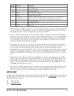
1. If you are using a dial-up modem to connect to your site, first install the PC modem according to
manufacturer’s instructions. If you are using the recommended U.S. Robotics 56K V.92 external dial-up
modem with the GSC3000, configure the DIP switch settings as shown on the following page.


