GSC3000 / LYNX 4 QUICK START GUIDE
3
After the modem is configured, connect it to any I/O or Voice Interface unit at your site, using COM2 for
an I/O or COM1 for a Voice Interface. Use the supplied DB9-25 straight-through cable. Then connect
the modem to the RJ-11 wall jack and cycle the power on the GSC3000.
2. If you are using a full-time modem to connect to your site, refer to pages 44-45 of the Installation and
Operations manual for configuration instructions. After configuring the modems, use the supplied DB9-25
straight-through cables to connect the studio modem to an available COM port on your PC and COM1
on an I/O unit. Do not connect a full-time modem to a Voice Interface or to COM2 on the I/O. Power
cycle the GSC3000 after connecting the modem.
3. Connect the input channels to the Wiring Interface unit by wiring your site equipment to the included
two-terminal push-on blocks and connecting the blocks to the rear panel of the wiring interface. For an
I/O-16 (sixteen channels of metering, status and command), use two Wiring Interfaces, with one
designated for metering and the other for status. For an I/O 8, connect your metering and status channels
to the same wiring interface. When you are done, use the supplied DB-37 connector to link the Wiring
Interface to the METERING or STATUS port on the I/O 16, or the METERING/STATUS port on an I/O 8
unit.
4. Connect the command channels to the Command Relay by wiring your site equipment to the included
three-terminal push-on blocks and connecting the blocks to the rear panel of the Command Relay. The
Command Relay supports eight command channels; use two Command Relays for sixteen channels of
command. Use the supplied DB-37 connector to link the Command Relay to the COMMAND 1-8 or the
COMMAND 9-16 port on the I/O unit.
5. After your I/O and Voice Interface units are configured, your communication equipment installed, and the
input and command channels connected, your site is ready for operation. Refer to the Installation and
Operations manual for details on the monitoring and control capabilities of the system.
GETTING HELP
Detailed setup and configuration instructions may be found in the Installation and Operations manual. If you still
need help, please visit the support section of the Burk Technology web site at www.burk.com, or contact Burk
Technology customer support.
Tel:
978-486-3711
Fax:
978-486-0081
Email: support@burk.com
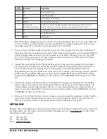
DIP
SWITCH
POSTION
FUNCTION
1
UP
Data Terminal Ready
2
UP
Verbal Result Codes
3
DOWN
Enables Result Code Display
4
DOWN
No echo, offline commands
5
UP (I/O unit)
DOWN (Voice Interface)
Enables auto answer. The modem will answer the incoming call for the I/O unit.
Disables auto answer. The voice interface will automatically answer the call.
6
UP
Carrier detect normal
7
UP
Load NVRAM defaults
8
DOWN
Smart mode


