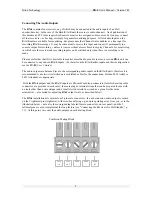
RX-4
Front Panel
Cover
⇐
Plates
Removed
NOTE: The type, number, and positions of the various receiver modules represent the standard configuration. Your unit may have been ordered with a different modular configuration; if so, disregard the illustrated left-to-right ordering of the
individual receiver units and reference them instead by type. If you’re not certain which receiver type occupies a particular module, they can be readily distinguished from one another by the number and arrangement of their tuning switches;
refer to the Tuning Control illustrations on pp. 15, 17 and 19.
1
2
9
10
11
12
17
18
19
20
3
4
25
26
27
28
33
34
36
35
Receiver Module #1 (AM)
Receiver Module #2 (FM)
Receiver Module #3 (FM)
Receiver Module #4 (WX)
Monitor Section
6
7
8
14
15
16
22
23
24
30
31
32
5
13
21
29
Summary of Contents for RX-4
Page 2: ...RX 4 User s Manual Version 1 01 BURK Technology ...
Page 4: ...RX 4 User s Manual Version 1 01 BURK Technology ii ...
Page 17: ...BURK Technology RX 4 User s Manual Version 1 01 13 ...
Page 28: ...RX 4 User s Manual Version 1 01 BURK Technology 24 APPENDIX RX 4 SCHEMATICS ...
Page 29: ...BURK Technology RX 4 User s Manual Version 1 01 25 ...
Page 31: ......
Page 32: ...RX 4 User s Manual Version 1 01 BURK Technology 4 ...
Page 33: ...BURK Technology RX 4 User s Manual Version 1 01 5 ...
Page 34: ...RX 4 User s Manual Version 1 01 BURK Technology 6 ...

