C
CO
OM
M1
1
Standard RS-232 DB9 connector to use with the supplied null-modem cable.
Connects to either a dial-up modem or your computer COM port for uploading
firmware. COM1 is also used for establishing a direct connection with a PC.
Wiring Interface Unit
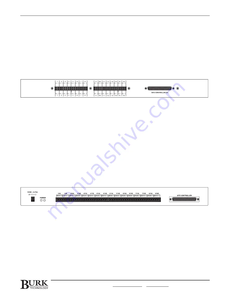
The Wiring Interface facilitates the connection of your site equipment to the GSC3000 or VRC2500. It
supports 16 metering or status inputs (use two Wiring Interfaces to fully utilize the VRC2500 or GSC3000 I/O
16 channel capacity). It has no front panel controls.
Note: If you are using a GSC3000 I/O 8, connect your metering and status inputs into a single Wiring Interface.
C
Ch
ha
an
nn
ne
ell C
Co
on
nn
ne
ecctto
orrss
Accepts two-terminal push-on-block connectors to accommodate up to 16 metering
or status channels from your site equipment. If you are using an I/O 16, you will
need two Wiring Interfaces to make all the connections.
S
Siitte
e C
Co
on
nttrro
olllle
err
Connects to the metering or status connection on the VRC2500 or GSC3000 I/O
unit using the included DB37-to-DB37 cable.
Note: See page 56 for instructions on connecting site equipment to the Wiring Interface. For input specifications, see
Appendix B.
Command Relay Unit
The Command Relay unit provides isolation between the GSC3000 or VRC2500 solid-state open-collector
outputs and your equipment. Each Command Relay Unit connects up to eight command output channels on
your system, each with two command states per channel. It has no front panel controls.
Note: See page 58 for instructions on connecting site equipment to the Command Relay. For command output
specifications, see Appendix B.
P
Po
ow
we
err LLE
ED
D
Indicates power to the Command Relay (received from the I/O unit). When the I/O
unit is powered up, both power LEDs on the command relay should be green,
indicating 5VDC power.
C
Ch
ha
an
nn
ne
ell C
Co
on
nn
ne
ecctto
orrss
Accepts three-terminal push on blocks to link the Command Relay to your site
equipment.
S
Siitte
e C
Co
on
nttrro
olllle
err
Connects to the Command 1-8 or Command 9-16 connection on the system.
Note: The power connector on the left side of the rear panel is for VRC1000 and 2000 systems and is
not used with
the GSC3000 or VRC2500.
CHAPTER 1: INTRODUCTION
13
CUSTOMER SUPPORT: 978-486-3711 • support@burk.com • www.burk.com
Summary of Contents for GSC3000
Page 8: ...GSC3000 VRC2500 INSTALLATION OPERATION MANUAL viii ...
Page 22: ...GSC3000 VRC2500 INSTALLATION OPERATION MANUAL 14 ...
Page 32: ...GSC3000 VRC2500 INSTALLATION OPERATION MANUAL 24 ...
Page 40: ...GSC3000 VRC2500 INSTALLATION OPERATION MANUAL 32 ...
Page 52: ...GSC3000 VRC2500 INSTALLATION OPERATION MANUAL 44 ...
Page 68: ...GSC3000 VRC2500 INSTALLATION OPERATION MANUAL 60 ...
Page 120: ...GSC3000 VRC2500 INSTALLATION OPERATION MANUAL 112 ...
Page 128: ...GSC3000 VRC2500 INSTALLATION OPERATION MANUAL 120 ...
Page 132: ...GSC3000 VRC2500 INSTALLATION OPERATION MANUAL 124 ...
Page 140: ...GSC3000 VRC2500 INSTALLATION OPERATION MANUAL 132 ...
Page 144: ...GSC3000 VRC2500 INSTALLATION OPERATION MANUAL 136 ...


