GSC3000 & VRC2500 INSTALLATION & OPERATION MANUAL
CHAPTER 6: MODEM & SITE EQUIPMENT CONNECTIONS
56
CONNECTING A WIRING INTERFACE
The Wiring Interface uses push-on blocks to simplify the connection of metering and status inputs to your
GSC3000 I/O or VRC2500 unit. No soldering is required. To utilize all input channels on a VRC2500 or a
GSC3000 I/O 16, you will need two wiring interfaces.
Voltage Inputs
The Wiring Interface is designed for status inputs of
±
30VDC and metering inputs of 0-10VDC or -5 to +5VDC
(specified when you configure the channel in Lynx). Metering samples should be at least 2VDC to provide
accurate readings. If the sample voltage is too small, a large calibration constant is required and may result in
widely fluctuating readings.
Floating Grounds
The GSC3000 and VRC2500 units will not tolerate a floating ground. If any of your inputs has a floating
ground, use an isolation amplifier before connecting it to the Wiring Interface.
Connecting Input Channels
To connect inputs:
1. If you have two Wiring Interfaces, you must designate one for status and one for metering channels. For
GSC3000 I/O 8 units only, the Wiring Interface will be used for both metering and status inputs.
Note: When using the Wiring Interface with an I/O 8, connect metering
inputs to the channels on the Wiring Interface marked 1-8, and connect
Status to 9-16.
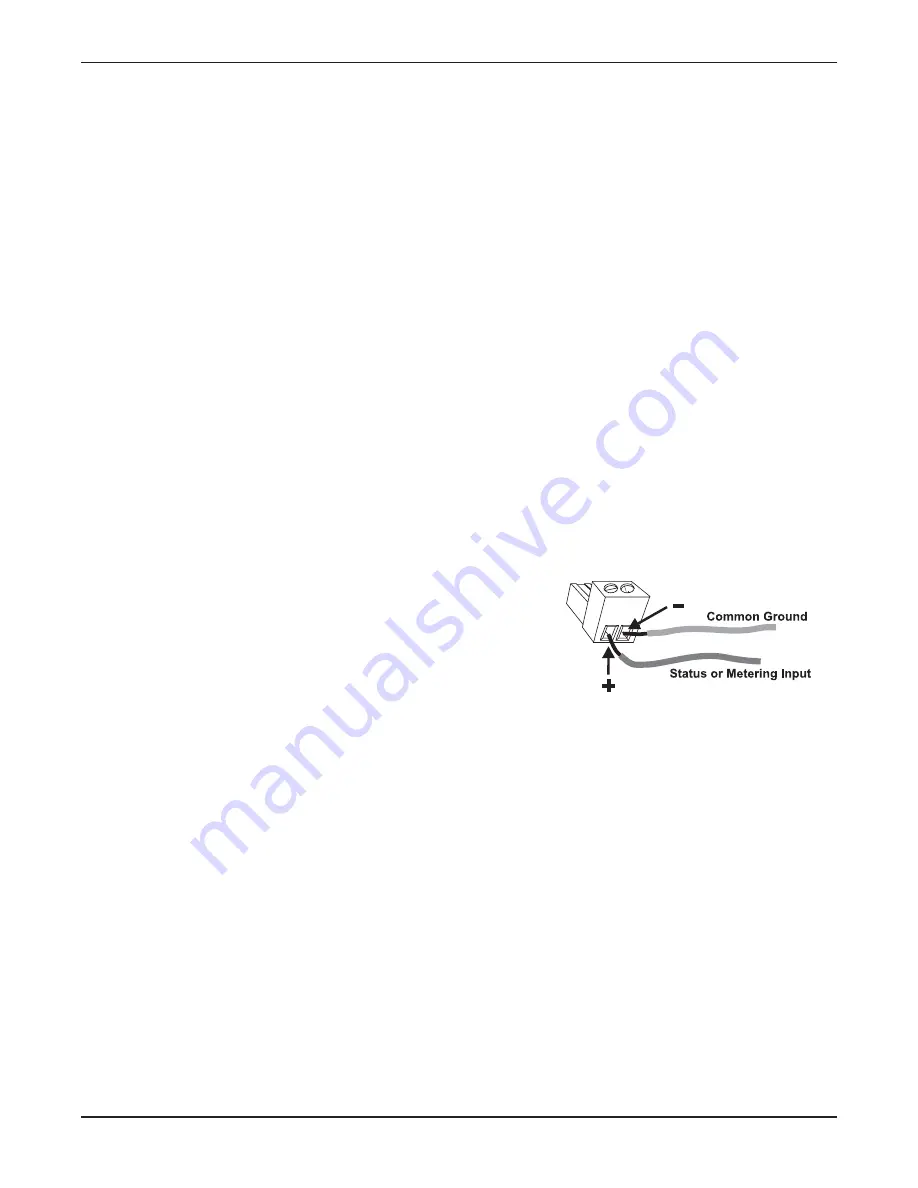
2. Connect the site equipment input wires to the Wiring
Interface push-on block and secure the wires with the built-in
setscrews. The status or metering input connects to the +
+
terminal, and a common ground connects to the –
– terminal.
3. Connect the push-on blocks to the Wiring Interface with the setscrews facing up. Be sure to precisely
align the connector terminals to the +
+ and –
– contacts on the back panel of the Wiring Interface.
Misalignment will result in faulty readings and may damage the I/O unit. If you set up all your channel
properties (labels, limits, alarms, etc.) in Lynx before installing the Wiring Interface, be sure to connect
your equipment to the channels you specified during unit configuration.
4. Use the provided DB37 cable to connect the SITE CONTROLLER I/O port on the Wiring Interface to the
METERING or STATUS port (as appropriate) on the VRC2500 or GSC3000 I/O 16 unit. An I/O 8 has
one METERING/STATUS port for both types of inputs.
Summary of Contents for GSC3000
Page 8: ...GSC3000 VRC2500 INSTALLATION OPERATION MANUAL viii ...
Page 22: ...GSC3000 VRC2500 INSTALLATION OPERATION MANUAL 14 ...
Page 32: ...GSC3000 VRC2500 INSTALLATION OPERATION MANUAL 24 ...
Page 40: ...GSC3000 VRC2500 INSTALLATION OPERATION MANUAL 32 ...
Page 52: ...GSC3000 VRC2500 INSTALLATION OPERATION MANUAL 44 ...
Page 68: ...GSC3000 VRC2500 INSTALLATION OPERATION MANUAL 60 ...
Page 120: ...GSC3000 VRC2500 INSTALLATION OPERATION MANUAL 112 ...
Page 128: ...GSC3000 VRC2500 INSTALLATION OPERATION MANUAL 120 ...
Page 132: ...GSC3000 VRC2500 INSTALLATION OPERATION MANUAL 124 ...
Page 140: ...GSC3000 VRC2500 INSTALLATION OPERATION MANUAL 132 ...
Page 144: ...GSC3000 VRC2500 INSTALLATION OPERATION MANUAL 136 ...


