60
Installation
fluid installation
8.5.
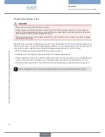
DANgEr!
risk of injury from high pressure in the equipment!
Before dismounting pneumatic lines and valves, turn off the pressure and vent the lines.
•
Design the connections with the largest possible volume.
•
Close the open connections not required with lock screws.
•
The connections for the pilot control exhaust air (x) must not be sealed.
•
Check that connections 1 and 3 or 5 have been configured correctly; these must not be mixed up.
•
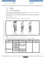
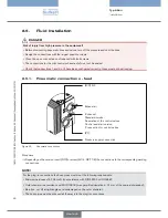
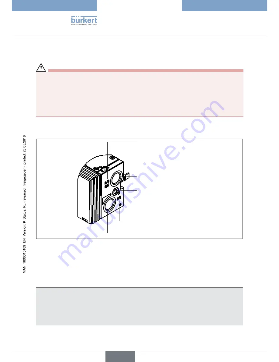
pneumatic connections - feed
8.5.1.
Exhaust air
Pressure supply connection
X channel:
Standard version:
Deaeration of the control valves
Control assist air version:
P connection for control valves
(R/S) 3/5
(P) 1
Pneumatic connections
Figure 33:
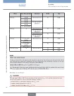
Procedure
Depending on the version, insert (D10) or screw (G1/4, NPT 1/4) the connections to the corresponding working
→
connections.
NoTE!
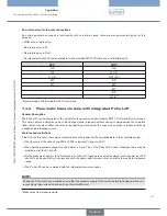
For the plug-in connections the hose pipes must meet the following requirements:
Minimum hardness of 40 Shore D (in accordance with DIN 53505 or ISO 868);
•
Outer diameter in accordance with DIN 73378 (max. permitted deviation ± 0.1 mm of the nominal dimension);
•
Burr-free, cut off at right angles and undamaged on the outer diameter;
•
The hose pipes must be pressed all the way into the plug-in connections.
•
Typ 8644
deutsch
Summary of Contents for 8644 AirLINE
Page 69: ......
Page 70: ...www burkert com ...


