background image

Quickstart

Type   8025 / 8035

Flowmeter 

English

Summary of Contents for 8025 Series

Page 1: ...Quickstart Type 8025 8035 Flowmeter English ...

Page 2: ...kstart 1312 0_EU ML 00565666 ORIGINAL_FR 1 About the Quickstart 3 2 Intended use 4 3 Basic safety information 4 4 General information 6 5 Description of the name plate 6 6 Technical data 7 7 Installation 13 8 Wiring 20 9 Installation and commissioning 49 10 Maintenance and troubleshooting 55 11 Packaging Transport 55 13 Disposal of the product 56 ...

Page 3: ...ickstart The quickstart describes the life cycle of the device Please keep this manual in a safe place accessible to all users and any new owners Important safety information Respect the safety instructions Study in particular the chapters entitled Intended Use and Basic Safety Instructions The quickstart must be read and understood The quickstart explains how to install set and start up the devic...

Page 4: ...nd maintenance Only use the device as intended Observe any existing restraints when the device is exported 3 Basic safety information This safety information does not take into account any contingencies or occurences that may arise during installation use and maintenance of the devices the local safety regulations for which the operating company is responsible including the staff in charge of inst...

Page 5: ...e operating instructions to observe the general technical rules when installing and using the device note The device may be damaged by the fluid in contact with Systematically check the chemical compatibility of the compo nent materials of the device and the fluids likely to come into contact with it for example alcohols strong or concentrated acids aldehydes alkaline compounds esters aliphatic co...

Page 6: ...ting condi tions specified in this manual 4 3 Information on the Internet You can find the operating instructions and technical data sheets regarding the type 8025 or the type 8035 or at www burkert com 5 Description of the name plate FLOW SE35 8035 HALL SUPPLY 12 36V 70 mA Output 1x4 20mA IP65 2xRel 30V and 42V peak or 60V max S N 11 026 00552726 W44MG Made in France 1 2 6 7 9 10 4 8 3 5 1 Measur...

Page 7: ...61010 1 Installation category UR and CSA recognized versions Category I according to UL61010 1 Max height above sea level 2000 m Protection rating 8025 compact and 8035 8025 wall mounted Housing panel version non front parts panel mounted version According to EN 60529 IP65 device wired and cable glands tightened and cover lid screwed tight IP65 device wired cable glands tightened cover lid screwed...

Page 8: ...ass or stainless steel The UL recognized devices with variable key PU01 comply with the fol lowing standards UL 61010 1 CAN CSA C22 2 n 61010 1 6 3 General data Pipe diameter 8025 flowmeter 8025 transmitter remote versions 8035 flowmeter DN20 except for the DN specified p 15 to DN400 DN06 to DN400 DN06 to DN65 Type of fitting S020 for a compact 8025 S030 for a 8035 Type of fluid liquid viscosity m...

Page 9: ...ch in procedure with the K factor of the fitting used Linearity 1 Repeatability 1 0 3 m s to 10 m s 0 5 m s to 10 m s 1 of the measured value at the value of the teach in flow rate 2 5 of the measured value 0 5 of the full scale 0 4 of the measured value 1 Determined in the following reference conditions medium water water and ambient temperatures 20 C min upstream and downstream distances respect...

Page 10: ...8025 compact versions 8025 remote versions 8035 PVDF Refer to the operating instruc tions of the remote sensor Refer to the operating instruc tions of the S030 sensor fitting Axis and bearings of the paddle wheel 8025 compact versions 8025 remote versions 8035 Ceramics Refer to the operating instruc tions of the remote sensor Refer to the operating instruc tions of the S030 sensor fitting Seals 80...

Page 11: ...safe energy level oscillation rate 10 Power supply not supplied limited power source according to 9 3 of EN 61010 1 standard or class 2 source according to UL 1310 1585 and EN 60950 1 standards Power supply 115 230 V AC frequency supplied voltage current integrated protection power 50 60 Hz 27 V DC regulated max 250 mA 250 mA time delay fuse Compact version 6 VA Wall mounted version 3 VA Currentco...

Page 12: ...ustable thresholds normally open 230 V AC 3 A 30 V AC max and 42 V peak or 60 V DC max Current output response time 10 to 90 max loop impedance 12 36 V DC version max loop impedance 115 230 V AC version wiring version without relays wiring version with relays 4 20 mA sinking or sourcing mode through wiring 5 75 s default 900 W at 30 V DC 600 W at 24 V DC 50 W at 12 V DC 800 W 2 wire 3 wire Protect...

Page 13: ...injury due to unintentional switch on of power supply or uncontrolled restarting of the installation Take appropriate measures to avoid unintentional activation of the installation Guarantee a set or controlled restarting of the process subse quent to any intervention on the device 6 7 Electrical connection Version Wiring features With male fixed connector Female connector type 2508 supplied For t...

Page 14: ...tive 97 23 EC Protect this device against electromagnetic inter ference ultraviolet rays and when installed outdoors the effects of the climatic conditions 7 2 Installation of a compact version 7 2 1 Instructions for installing a compact version onto the pipe The 8025 flowmeter has to be inserted into an S020 fitting mounted on a pipe The 8035 flowmeter has to be installed on the pipe using the S0...

Page 15: ... 5 10 0 01 0 02 0 05 0 1 0 2 0 5 1 2 5 10 20 50 100 200 m3 h l min 0 3 0 5 1 3 5 10 30 m s fps gpm 0 05 0 1 0 2 0 5 1 2 5 10 20 50 100 200 500 1000 DN65 DN50 DN65 DN40 DN50 DN32 DN40 DN25 DN32 DN20 DN25 DN15 DN15 DN20 DN08 DN06 0 2 0 5 1 2 5 10 20 50 100 200 500 1000 2000 3000 Example Flow rate Flow velocity Example Specification if the nominal flow rate is 10 m3 h the ideal flow velocity is betwe...

Page 16: ...sions Pipe with 2 elbows at 90 Pipe with 1 elbow at 90 or 1 T piece With pipe expansion With pipe reduction Fig 4 Upstream and downstream distances depending on the design of the pipes Ensure that the pipe is always filled in the section around the device see Fig 5 When mounting vertically ensure that the flow direction is in an upward direction see Fig 5 Horizontal mounting Correct Incorrect Vert...

Page 17: ... into the pipe obeying the instructions in chap 7 2 1 Check that there is a seal on the fitting and that it is not damaged Replace the seal if necessary Insert nut 3 on fitting 5 Insert snap ring 2 into groove 4 Check that seal 6 is correctly inserted on the flow sensor Insert device 1 into the fitting If the mounting is correctly done the device cannot be turned around anymore Hand lock the assem...

Page 18: ... module to the sensor fitting Fig 8 Installation of the SE35 onto the S030 sensor fitting 7 3 Installation of a panel version of the 8025 flowmeter Install the panel version of the device in a cabinet with a protection class at least IP54 to ensure a degree of pollution 2 inside the cabinet To cut the opening in the cabinet door use the supplied cutting plan of the frontage of the electrical cabin...

Page 19: ...and tighten the nuts to secure the device to the cabinet Wire according to the instructions in chapter 8 7 4 Installation of a wall mounted version of the 8025 flowmeter note Risk of material damage if the cable glands are not tightly screwed on the housing Before installing the wall mounted housing on its support tighten the nuts of the entry item of the cables glands at a torque of 1 5 Nm The fl...

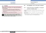
Page 20: ... respecting the dimensions indicated in Fig 11 Wire acc to instructions in chap 8 Close the housing and tighten the 4 screws of the cover 8 Wiring danger Risk of injury due to electrical voltage Shut down the electrical power source of all the conductors and isolate it before carrying out work on the system Observe all applicable accident protection and safety regula tions for electrical equipment...

Page 21: ...r supply device fluid Connect together the various earth spots in the installation to eliminate the potential differences that may occur between dif ferent earthes Observe faultless earthing of the shield of the power supply cable at both ends Connect the negative power supply terminal to the earth to sup press the effects of common mode currents If this connection cannot be made directly a 100 nF...

Page 22: ...pact version and 8035 equipotentiality skeleton diagram with metal or plastic pipes 8025 8030 Power supply Panel or wall mounted version Metal pipes 8025 8020 Power supply Valve pump or earth rings not provided inserted into the pipe Plastic pipes Panel or wall mounted version If a direct earth connection is not possible fit a 100 nF 50 V capacitor between the negative power supply terminal and th...

Page 23: ...h the cable gland and finally through the housing 2 Connect the wires on terminal block 3 see Fig 14 Fig 16 and Fig 17 Position the terminal block 3 in steps of 90 then put it back into the housing 2 pulling gently on the cable so that the wires do not clutter the housing Tighten the nut 1 on the cable gland 6 5 Place the seal 5 between the connector and the fixed con nector on the device and then...

Page 24: ...ssible wiring of the current output of a compact version with male fixed connector Wire the transistor output using one of the wiring plans of Fig 17 Wiring of the pulse output in NPN mode 300 mA 12 36 V DC 1 3 2 L L P P 8025 NPN P P 5 36 V DC Power supply PLC Wiring of the pulse output in PNP mode 300 mA 12 36 V DC 1 3 2 L L P P 8025 PNP P P 5 36 V DC Power supply PLC If direct earthing is not po...

Page 25: ...hout With Relays FLOW SENSOR COIL NPN PE Fig 18 Position of the FLOW SENSOR connector on the electronic board Table 2 Positioning of the FLOW SENSOR selector depending on the output signal of the flow sensor Version of the flowmeter Output signal of the remote sensor Position of the FLOW SENSOR selector All Pulse NPN hall NPN All Sinus coil COIL 8 3 2 SOURCE SINK selector The Source Sink selector ...

Page 26: ... with a 115 V AC voltage Fig 20 Selector of the supply voltage on a 115 230 V AC version 8 4 Wiring the 8025 in compact version and the 8035 with or without relays with cable glands 8 4 1 Wiring instructions Seal the unused cable gland using the stopper gasket sup plied to make sure the device is tight Unscrew the nut of the cable gland Remove the transparent disc inside the cable gland Insert the...

Page 27: ...nds Set the selectors according to chap 8 3 Connect the terminal block according to the indications of chap 8 4 2 to 8 4 6 8 4 2 Wiring of the relays versions with relay output Supply 12 36Vdc FLOW SENSOR COIL NPN SOURCE SINK L L PE P P NC L L PE P P Iout PULSE OUTPUT Without With Relays 2 1 3 PE 1 relay 1 connection 2 relay 2 connection 3 fixation slots Always secure the relays connection cables ...

Page 28: ... P P Iout PULSE OUTPUT Without With Relays PE 3 2 1 A Terminal block 1 NC not connected L positive power supply L negative power supply PE wiring of the PE between the main board and the protection board P negative pulse output P positive pulse output Terminal block 2 PE Wiring of the cable shields Connector 3 connection of the flow sensor Switch A see chap 8 3 1 Fig 23 Terminal assignment of a 12...

Page 29: ... of the current output of a compact version 12 36 VDC without relays with cable glands Wiring of the pulse output in NPN mode Supply 12 36Vdc FLOW SENSOR COIL NPN L L PE P P NC L L PE P P Iout PULSE OUTPUT Without With Relays 300 mA 12 36 V DC 8025 NPN P P 5 36 V DC PE PLC Power supply Wiring of the pulse output in PNP mode Supply 12 36Vdc FLOW SENSOR COIL NPN L L PE P P NC L L PE P P Iout PULSE O...

Page 30: ...L positive power supply L negative power supply PE wiring of the PE between the main board and the protection board P negative pulse output P positive pulse output Terminal block 2 PE Wiring of the cable shields Connector 3 connection of the flow sensor Terminal block 4 wiring of relay 1 see chap 8 4 2 Terminal block 5 wiring of relay 2 see chap 8 4 2 Jumper wire 6 Jumper wire to be removed if the...

Page 31: ... L L PE P P Iout PULSE OUTPUT Without With Relays Iout 300 mA 12 36 V DC PE Wiring of the current output in sinking mode Power supply 4 20mA input at external instrument Source Sink selector see chap 8 3 2 If direct earthing is not possible insert a 100 nF 50 V condensator between the negative terminal of the voltage supply and the earth If the current output is wired remove the jumper wire betwee...

Page 32: ... FLOW SENSOR COIL NPN SOURCE SINK L L PE P P NC L L PE P P Iout PULSE OUTPUT Without With Relays 300 mA 12 36 V DC P P 8025 PNP 5 30 V DC PE Wiring of the pulse output in PNP mode PLC Power supply If direct earthing is not possible insert a 100 nF 50 V condensator between the negative terminal of the voltage supply and the earth Fig 28 Wiring in NPN or PNP mode of the pulse output of a compact ver...

Page 33: ... chap 8 3 3 Terminal block 1 NC not connected terminal for the wiring of the 4 20 mA output L red wire factory wired PE wiring of the PE between the main board and the protection board L black wire factory wired P negative pulse output P positive pulse output Terminal block 2 PE Shield connection green yellow wire factory wired Connector 3 connection of the flow sensor Jumper wire 4 jumper wire to...

Page 34: ...If the current output is wired remove the jumper wire between the terminals Iout and L Fig 30 Wiring of the current output of a compact version 115 230 V AC without relays with cable glands Wiring of the pulse output in NPN mode Supply 12 36Vdc FLOW SENSOR COIL NPN L L PE P P NC L L PE P P Iout PULSE OUTPUT Without With Relays 230V T 125 mA N PE L 5 36 V DC 8025 NPN P P PE 115 230 V AC power suppl...

Page 35: ...t With Relays 230V T 125 mA N PE L 5 36 V DC 8025 PNP P P PE 115 230 V AC power supply PLC If direct earthing is not possible insert a 100 nF 50 V condensator between the negative terminal of the voltage supply and the earth Fig 31 Wiring in NPN or PNP mode of the pulse output of a 115 230 V AC compact version without relays with cable glands English ...

Page 36: ...re factory wired PE wiring of the PE between the main board and the protection board P negative pulse output P positive pulse output Terminal block 2 PE Shield connection green yellow wire factory wired Connector 3 connection of the flow sensor Terminal block 4 wiring of relay 1 see chap 8 4 2 Terminal block 5 wiring of relay 2 see chap 8 4 2 Jumper wire 6 jumper wire to be removed if the 4 20 mA ...

Page 37: ...Wiring in sourcing mode of the current output of a compact version 115 230 V AC with relays with cable glands 115 230 V AC power supply 4 20mA input at external instrument Supply 12 36Vdc FLOW SENSOR COIL NPN SOURCE SINK L L PE P P NC L L PE P P Iout PULSE OUTPUT Without With Relays N PE L 230V T 125 mA PE If the current output is wired remove the jumper wire between the terminals Iout and L Fig 3...

Page 38: ...f direct earthing is not possible insert a 100 nF 50 V condensator between the negative terminal of the voltage supply and the earth Fig 35 Wiring in NPN or PNP mode of the pulse output of a 115 230 V AC compact version with relays with cable glands Connect the relays according to chap 8 4 2 8 5 Connecting the flow sensor to the 8025 transmitter panel mounted version or wall mounted version Config...

Page 39: ...6 Wiring of the remote flow sensor to the 8025 transmitter 8 6 Wiring the 8025 remote wall mounted or panel 12 36 V DC with or without relays 8 6 1 Wiring the 8025 remote version 12 36 V DC without relays For a wall mounted version obey the wiring instructions of chap 8 7 1 Configure the FLOW SENSOR selector on the electronic board see chap 8 3 Connect the flow sensor to the transmitter according ...

Page 40: ...board P negative pulse output P positive pulse output Terminal block 2 PE Wiring of the cable shields Connector 3 connection of the flow sensor see chap 8 5 Fig 37 Terminal assignment of a panel mounted or wall mounted version 12 36 V DC without relays The wiring of the current output and the wiring of the pulse output of the panel or wall mounted transmitter 12 36 V DC without relays are the same...

Page 41: ...OIL SENSOR 1 2 3 NC 4 NC 4 6 3 5 A 2 1 B PE Switch A see chap 8 3 1 Switch B see chap 8 3 2 Terminal block 1 Iout 4 20 mA output L positive power supply L negative power supply PE wiring of the PE between the main board and the protection board P negative pulse output P positive pulse output Terminal block 2 PE Wiring of the cable shields Terminal block 3 wiring of relay 1 see chap 8 4 2 Terminal ...

Page 42: ...electronic board see chap 8 3 Loosen the nuts of the cable glands Insert each cable through a nut then through the cable gland using the cable glands as shown in Fig 39 Flow sensor cable Cables of the outputs Power supply cable 12 36 V DC or 115 230 V AC Fig 39 Using the cable glands Remove the two terminal blocks marked 4 and 6 in Fig 40 chap 8 7 2 and Fig 44 chap 8 7 3 from the housing For the v...

Page 43: ...ed L green wire factory wired PE wiring of the PE between the main board and the protection board P brown wire factory wired P white wire factory wired Terminal block 2 PE Shieldwiring green yellowwire factorywired Time delay fuse 3 fuse to protect the 115 V AC or 230 V AC power supply Terminal block 4 wiring of the 115 230 V AC power supply Jumper wire 5 jumper wire to be removed if the 4 20 mA o...

Page 44: ...V PE 4 20mA input at external instrument Fig 41 Wiring of the current output of a wall mounted version without relays Supply 12 36Vdc NPN SENSOR 1 PULSE INPUT 2 3 4 NC SUPPLY 1 2 3 4 PE REL1 REL2 FLOW SENSOR FLOW SENSOR COIL NPN COIL SENSOR 1 2 3 NC 4 NC L L PE P P NC L L PE P P Iout PULSE OUTPUT Without With Relays 230V L N 230V T 250 mA 5 6 7 8 9 10 L N 230V 5 36 VDC PE Fig 42 Wiring in NPN mode...

Page 45: ...4 PE REL1 REL2 FLOW SENSOR FLOW SENSOR COIL NPN COIL SENSOR 1 2 3 NC 4 NC L L PE P P NC L L PE P P Iout PULSE OUTPUT Without With Relays 230V L N 230V T 250 mA 5 6 7 8 9 10 L N 230V 5 36 V DC PE Fig 43 Wiring in PNP mode of the pulse output of a wall mounted version without relays English ...

Page 46: ...c NPN SENSOR 1 PULSE INPUT 2 3 4 NC SUPPLY 1 2 3 4 PE 3A 230VAC REL1 REL2 FLOW SENSOR FLOW SENSOR COIL NPN CURRENT SOURCE SINK COIL SENSOR 1 2 3 NC 4 NC L L PE P P NC L L PE P P Iout PULSE OUTPUT Without With Relays 230V T 250 mA L N 230V 5 6 7 8 9 10 L N 230V 7 5 3 10 9 8 2 1 A B 4 6 C PE Switch A see chap 8 3 1 Switch B see chap 8 3 3 Switch C see chap 8 3 2 English ...

Page 47: ... Jumper wire 5 jumper wire to be removed if the 4 20 mA output is connected Terminal block 6 Terminal 5 4 20 mA output Terminal 6 positive 27 V DC power supply available to energize an external instrument Terminal 7 0V earth of the power supply available to energize an external instrument Terminal 8 cable shields Terminal 9 negative pulse output Terminal 10 positive pulse output Marker 7 all the c...

Page 48: ...V T 250 mA L N 230V 5 6 7 8 9 10 L N 230V PE 4 20mA input at external instrument Fig 45 Wiring in sinking mode of the current output of a wall mounted version 115 230 V AC with relays Supply 12 36Vdc NPN SENSOR 1 PULSE INPUT 2 3 4 NC SUPPLY 1 2 3 4 PE 3A 230VAC REL1 REL2 FLOW SENSOR FLOW SENSOR COIL NPN CURRENT SOURCE SINK COIL SENSOR 1 2 3 NC 4 NC L L PE P P NC L L PE P P Iout PULSE OUTPUT Withou...

Page 49: ...mmissioning make sure that the staff in charge have read and fully understood the contents of the manual Inparticular observethesafetyrecommendationsandintendeduse The device the installation must only be commissioned by suit ably trained staff Before commissioning set the K Factor of the fitting used See chap 9 6 9 2 Operating levels of the device The device has two operating levels the Process l...

Page 50: ...ACTOR Current PULSE Relay FILTER total END 12 6 L MIN 16 45 ma 87654 l 231 l offset span frequenc flow END 0 9 0 9 0 9 0 9 ENTER ENTER 5 s 5 s Configuration level 0 9 2 s To reset the daily totalizer iden tified by a dot after the volume units Process level Fig 47 Diagram of the levels of the device English ...

Page 51: ...ed parameter Confirming the settings LED indicating the status of the relay 2 LED ON contact closed Scrolling through the parameters Selecting the figure on the left Scrolling up the parameters Incrementing the figure selected LED indicating the status of the relay 1 LED ON contact closed Fig 48 Description of the display English ...

Page 52: ...r 5 s in the Process level access the Test menu 0 9 ENTER simultaneously for 5 s in the Process level reset the daily totalizer from the Process level 0 9 simultaneously for 2 s when the daily totalizer is displayed in the Process level select the displayed parameter ENTER confirm the displayed value ENTER modify a numerical value 0 9 to increase the blinking digit to select the digit at the left ...

Page 53: ... not want to adjust another parameter go to the END parameter of the Parameters menu and press ENTER to save the settings and go back to the Process level 9 6 Entering the K factor of the fitting used The device determines the flow rate in the pipe using the fitting K factor The K factor of the fitting used can be entered here The K factor of the fitting used is in the operating instruc tions of t...

Page 54: ... The display shows the K factor of the fitting last entered or determined using a Teach In procedure Edit the parameter Enter the K factor value between 0 0001 and 9999 9 of the fitting used Confirm the displayed value K FACTOR ENTER ENTER Fig 50 Entering the K factor of the fitting used English ...

Page 55: ...ed or controlled restarting of the process after a power supply interruption If any problem occurs refer to the complete operating instruc tions on the CD delivered with the device 11 Packaging Transport note Damage due to transport Transport may damage an insufficiently protected device Transport the device in shock resistant packaging and away from humidity and dirt Do not expose the device to t...

Page 56: ...g in an environmentally friendly way note Damage to the environment caused by products contami nated by fluids Keep to the existing provisions on the subject of waste disposal and environmental protection Note Comply with the national and or local regulations which concern the area of waste disposal English ...

Page 57: ...Quickstart Typ 8025 8035 Durchfluss Messgerät Deutsch ...

Page 58: ...start 1312 0_EU ML 00565666 ORIGINAL_FR 1 Der Quickstart 3 2 Bestimmungsgemässe Verwendung 4 3 Grundlegende Sicherheitshinweise 4 4 Allgemeine Hinweise 6 5 Beschreibung des Typschilds 6 6 Technische Daten 7 7 Installation 14 8 Verkabelung 21 9 Bedienung und Inbetriebnahme 52 10 Wartung Fehlerbehebung 59 11 Verpackung Transport 59 13 Entsorgung des Gerätes 60 ...

Page 59: ...szyklus des Gerätes Bewahren Sie diese Anleitung so auf dass sie für jeden Benutzer zugänglich ist und jedem neuen Eigentümer des Gerätes wieder zur Verfügung steht Wichtige Informationen zur Sicherheit Lesen Sie den Quickstart sorgfältig durch Beachten Sie vor allem die Kapitel Grundlegende Sicherheitshinweise und Bestimmungs gemäße Verwendung Der Quickstart muss gelesen und verstanden werden Der...

Page 60: ...dnungsgemäße Weise zu verwenden Beachten Sie bei der Ausfuhr des Gerätes gegebenenfalls bestehende Beschränkungen 3 Grundlegende Sicherheitshinweise Diese Sicherheitshinweise berücksichtigen keine Zufälligkeiten und Ereignisse die bei Montage Betrieb und Wartung der Geräte auftreten können OrtsbezogenenSicherheitsbestimmungen fürderenEinhaltung auchin Bezug aufdasInstallations undWartungspersonal ...

Page 61: ...ei der Einsatzplanung und dem Betrieb des Gerätes die allge meinen Regeln der Technik einhalten Hinweis Das Gerät kann durch das Medium beschädigt werden Kontrollieren Sie systematisch die chemische Verträglichkeit der Werkstoffe aus denen das Gerät besteht und die Medien die mit diesem in Berührung kommen können zum Beispiel Alko hole starke oder konzentrierte Säuren Aldehyde Basen Ester aliphati...

Page 62: ...r Beachtung der im vorliegenden Handbuch spezifizierten Einsatzbedingungen 4 3 Informationen im Internet Bedienungsanleitungen und Datenblätter zu dem Typ 8025 oder dem Typ 8035 finden Sie im Internet unter www buerkert de 5 Beschreibung des Typschilds FLOW SE35 8035 HALL SUPPLY 12 36V 70 mA Output 1x4 20mA IP65 2xRel 30V and 42V peak or 60V max S N 11 026 00552726 W44MG Made in France 1 2 6 7 9 1...

Page 63: ...gen Grad 2 nach EN 61010 1 Einbaukategorie UR und CSA recognized Ausführungen Kategorie I nach UL61010 1 Max Meereshöhe 2000 m Schutzart 8025 Kompakt und 8035 8025 Wandmontage Aus führung Schaltschrank Gehäuse Schaltschrank Ausführung innerhalb des Schranks Nach EN 60529 IP65 mit angeschlossenem Gerät und festgeschraubten Kabelverschraubungen und bis zum Anschlag festge schraubtem Deckel IP65 mit ...

Page 64: ...us PP PVC PVDF Messing oder Edelstahl Die UL Geräte mit variablem Bestell Schlüssel PU01 sind den folgenden Normen konform UL 61010 1 CAN CSA C22 2 n 61010 1 6 3 Allgemeine Daten Durchmesser der Rohrleitungen Durchfluss Messgerät 8025 Transmitter 8025 getrennte Ausführungen Durchfluss Messgerät 8035 DN20 außer die auf Seite 16 spezifizierten DN bis DN400 DN06 bis DN400 DN06 bis DN65 Typ des Fittin...

Page 65: ... Bild 3 PN10 PN10 PN16 PN40 auf Anfrage Durchflussmessung Messbereich Sensor mit Pulsausgang Hall Sensor mit Sinusausgang Spule Genauigkeit mit Kalibrierverfahren Teach In mit K Faktor des ver wenden Fittings Linearität 1 Wiederholbarkeit 1 0 3 m s bis 10 m s 0 5 m s bis 10 m s 1 vom Messwert beim Teach In Durchfluss 2 5 vom Messwert 0 5 vom Messbereichsende 0 4 vom Messwert 1 Unter folgenden Refe...

Page 66: ...tur Abhängigkeitskurven der Flüssigkeit für einen 8025 in Kompakt Ausführung je nach Werkstoff des Fittings S020 10 9 8 7 6 5 4 3 2 1 0 30 10 10 30 50 70 90 110 PVDF PN10 PVC PN10 PP PN10 PVC PP PVDF 16 15 14 13 12 11 A P bar T C A Metall A Verwendungsbereich Bild 3 Druck Temperatur Abhängigkeitskurven der Flüssigkeit für einen 8035 je nach Werkstoff des Fittings S030 deutsch ...

Page 67: ...iehe Bedienungsanleitung des Sensor Fittings S030 Dichtungen 8025 Kompakt Ausführungen 8025 getrennte Ausführungen FKM EPDM im Lieferumfang Siehe Bedienungsanleitung des abgesetzten Sensors Überwurfmutter 8025 Kompakt Ausführungen PC Teil Werkstoff Gehäuse 8025 Kompakt oder Schaltschrankmontage Aus führungen 8025 Wandmontage Ausführungen 8035 PC ABS PC Deckel 8025 Kompakt Ausfüh rungen oder 8035 8...

Page 68: ...z 27 V DC geregelt Max 250 mA 250 mA Zeitsicherung Kompakt Ausführung 6 VA Wandmontage Ausführung 3 VA Eigenverbrauch ohnedenVerbrauch des4 20mA Ausgangs Version 12 36 V DC mit Relais Version 12 36 V DC ohne Relais Version115 230VAC Kompakt Ausführung Version 115 230 V AC Wandmontage Ausführung max 70 mA bei 12 V DC max 25 mA bei 12 V DC max 125 mA bei 27 V DC max 250 mA bei 27 V DC Pulsausgang Ty...

Page 69: ...ische Daten der Last nicht UL Geräte Elektrische Daten der Last UL Geräte Hysterese einstellbare Schwellenwerte stromlos geöffnet 230 V AC 3 A max 30 V AC und 42 V Spitze oder max 60 V DC Stromausgang Ansprechszeit 10 bis 90 Max Schleifenimpendanz Version 12 36 V DC Max Schleifenimpendanz Version 115 230 V AC Verkabelung Version ohne Relais Verkabelung Version mit Relais 4 20 mA Quelle oder Senke ...

Page 70: ...lti Durchführungs Dichtung Mit Aderquerschnitt 0 2 bis 1 5 mm2 Alle Querschnitt der Ader der lokalen Erdung 0 75 mm2 7 Installation 7 1 Sicherheitshinweise Gefahr Verletzungsgefahr durch Stromschlag Schalten Sie vor Beginn der Arbeiten in jedem Fall alle exi stierenden am Gerät angeschlossenen Spannungs Ver sorgungen ab und sichern Sie diese vor unbeabsichtigtem Wiedereinschalten Beachten Sie gelt...

Page 71: ...tes Einschalten der Anlage und unkontrollierten Wiederanlauf Anlage vor unbeabsichtigtem Betätigen sichern Nach jedem Eingriff an dem Gerät einen kontrollierten Wieder anlauf gewährleisten Schützen Sie das Gerät vor elektromagnetischen Stö rungen U V Bestrahlung und bei Außenanwendung vor Witterungseinflüssen 7 2 Installation einer Kompakt Ausführung 7 2 1 Empfehlungen für die Montage einer Kompak...

Page 72: ... S030 0 1 0 3 0 5 1 3 5 10 0 01 0 02 0 05 0 1 0 2 0 5 1 2 5 10 20 50 100 200 m3 h l min 0 3 0 5 1 3 5 10 30 m s fps gpm 0 05 0 1 0 2 0 5 1 2 5 10 20 50 100 200 500 1000 DN65 DN50 DN65 DN40 DN50 DN32 DN40 DN25 DN32 DN20 DN25 DN15 DN15 DN20 DN08 DN06 0 2 0 5 1 2 5 10 20 50 100 200 500 1000 2000 3000 Beispiel Durchfluss Flüssigkeitsgeschwindigkeit Beispiel Anforderung Liegt der Durch fluss bei 10 m3 ...

Page 73: ...onen Rohrleitung mit 2 90 Krümmern Rohrleitung mit 1 90 Krümmer oder 1 T Stück Mit Rohraufweitung Mit Rohrreduzierung Bild 4 Mindestein und auslaufstreckenjenachAufbauderRohrleitungen Darauf achten dass die Rohrleitung im Bereich des Sensors immer gefüllt ist Bild 5 Sicherstellen dass bei der vertikalen Montage die Fließrichtung nach oben verläuft siehe Bild 5 Horizontale Montage Richtig Falsch Ve...

Page 74: ...dabei die Hinweise des Kap 7 2 1 beachten Prüfen ob die Dichtung auf dem Fitting sitzt und ob sie unversehrt ist Die Dichtung erforderlichenfalls ersetzen Überwurfmutter 3 auf Fitting 5 setzen Sprenging 2 in Rille 4 befestigen Prüfen ob Dichtung 6 richtig auf dem Durchfluss Sensor liegt Gerät 1 sorgfältig in das Fitting einsetzen Bei korrektem Einbau darf sich das Gerät nicht drehen lassen Gerät m...

Page 75: ...tting zu verriegeln Bild 8 Installation des SE35 auf ein Sensor Fitting S030 7 3 Installation eines 8025 in der Schaltschrankmontage Ausführung Die Schaltschrank Ausführung in einen Schaltschrank mit minimaler Schutzart IP54 installieren um einen Verschmutzungsgrad 2 innerhalb des Schaltschranks zu gewährleisten Die mitgelieferte Ausschneidschablone verwenden dabei die in Bild 9 angegebenen Maße f...

Page 76: ...as Gerät an den Schaltschrank mittels den 4 Überwurfmuttern befestigen Je nach Hinweise des Kap 8 verkabeln 7 4 Installation eines 8025 in der Wandmontage Ausführung Hinweis Gefahr vor Sachschäden wenn die Kabelverschraubungen nicht am Gehäuse befestigt sind Vor der Montage des Wandmontage Gehäuses die Zwischen stutzen der Kabelverschraubungen mit einem Drehmoment von 1 5 Nm anziehen Der Boden des...

Page 77: ... Hinweise des Kap 8 verkabeln Das Gehäuse schließen und die 4 Schrauben des Deckels festziehen 8 Verkabelung Gefahr Verletzungsgefahr durch Stromschlag Schalten Sie vor Beginn der Arbeiten in jedem Fall alle exi stierenden am Gerät angeschlossenen Spannungs Ver sorgungen ab und sichern Sie diese vor unbeabsichtigtem Wiedereinschalten Beachten Sie geltende Unfallverhütungs und Sicherheitsbe stimmun...

Page 78: ...pannung Gerät Flüssigkeit zu gewährleisten Die verschiedenen Erdungspunkte der Installation aneinander anschließen damit die zwischen zwei Erdungspunkten mögli cherweise erzeugten Potentialdifferenzen beseitigt werden Auf vorschriftsmäßige Erdung der Abschirmung des Versor gungskabels an beiden Enden achten Den Minuspol der Stromversorgung an die Erde anschließen um die Auswirkungen von Gleichtakt...

Page 79: ...lder einer Äquipotentialität bei Rohrleitung aus Metall oder Kunststoff 8025 8030 Versorgungsspannung Wandmontage oder Schalt schrank Ausführung Metallische Rohrleitungen 8025 8020 Versorgungsspannung Ventil Pumpe oder Erdungsringe nicht mitge liefert in der Rohrleitung eingefügt Kunststoff Rohrleitungen Wandmontage oder Schalt schrank Ausführung Wenn eine direkte Erdung nicht möglich ist einen Ko...

Page 80: ...mmleiste 3 aus dem Gehäuse 2 herausnehmen Das Kabel durch die Über wurfmutter 1 dann durch die Dichtung 4 und die Kabelver schraubung führen und schließlich in das Gehäuse 2 stecken Die Anschlüsse an der Schraub klemmleiste 3 vornehmen siehe Bild 14 Bild 16 und Bild 17 Die Klemmleiste 3 wie gewünscht in Schritten von 90 positionieren und dann wieder in das Gehäuse 2 einsetzen indemleicht amKabel g...

Page 81: ...ng und den Stromausgang gemäß einem der Schaltplänen in Bild 16 verkabeln 300 mA 12 36 V DC 1 3 2 L L Versorgungs spannung 4 20 mA Eingang am externen Instrument 4 20 mA Eingang am externen Instrument 300 mA 12 36 V DC 1 3 2 L L Versorgungs spannung Wenn eine direkte Erdung nicht möglich ist einen Kondensator mit 100 nF 50 V zwischen Minuspol der Stromversorgung und Erde anschließen Bild 16 Möglic...

Page 82: ...Einstellung der Auswahlschalter Die Auswahlschalter nur spannungsfrei einstellen Vor der Verkabelung des Geräts die Auswahlschalter auf der Elektronikplatine einstellen Siehe Kap 8 3 1 bis 8 3 3 8 3 1 Auswahlschalter FLOW SENSOR Der Auswahlschalter FLOW SENSOR dient zur Konfiguration des Durchfluss Sensors Spule oder Hall Effekt Bei einer Ausführung mit Gerätestecker wird der Auswahl schalter im W...

Page 83: ...L L PE P P NC L L PE P P Iout PULSE OUTPUT Without With Relays SOURCE SINK Without Relays PE Bild 19 Auswahlschalter Source Sink auf der Elektronikplatine Tab 3 Stelle des Auswahlschalters Source Sink je nach anschlussart des Stromausgangs einer Version mit Relais Anschluss des 4 20 mA Stromausgangs Stelle des Auswahlschalters Source Sink bei einer Version mit Relais Nicht verkabelt Drahtbrücke ei...

Page 84: ...r zurückschrauben Schraube aufdrehen und durchsichtige Klappe heben Die 4 Schrauben aufdrehen dann den Deckel des Gerätes abnehmen Bei einer Version mit Relais die Kabelschellen einsetzen Supply 12 36Vdc FLOW SENSOR COIL NPN SOURCE SINK L L PE P P NC L L PE P P Iout PULSE OUTPUT Without With Relays PE Bevor das Gerät verkabelt wird die mitgelieferten Kabel schellen auf der Elektronikplatine bzw au...

Page 85: ...c FLOW SENSOR COIL NPN SOURCE SINK L L PE P P NC L L PE P P Iout PULSE OUTPUT Without With Relays 2 1 3 PE 1 Anschluss Relais 1 2 Anschluss Relais 2 3 Befestigungsnuten Die Anschlusskabel der Relais müssen an die Befestigungs nuten 3 befestigt werden siehe Bild 21 Bild 22 Anschluss der Relais deutsch ...

Page 86: ... L PE P P Iout PULSE OUTPUT Without With Relays PE 3 2 1 A Klemmleiste 1 NC Nicht belegt L Positive Spannungsversorgung L Negative Spannungsversorgung PE Anschluss der PE zwischen Hauptplatine und Schutzplatine P Negativer Pulsausgang P Positiver Pulsausgang Klemmleiste 2 PE Anschluss der Abschirmungen der Kabel Stecker 3 Anschluss des Durchfluss Sensors Schalter A Siehe Kap 8 3 1 Bild 23 Klemmenb...

Page 87: ...smöglichkeiten des Stromausgangs einer Kompakt Ausführung 12 36 VDC ohne Relais mit Kabelverschraubungen NPN Anschluss des Pulsausgangs Supply 12 36Vdc FLOW SENSOR COIL NPN L L PE P P NC L L PE P P Iout PULSE OUTPUT Without With Relays 300 mA 12 36 V DC 8025 NPN P P 5 36 V DC PE SPS Versorgungsspannung PNP Anschluss des Pulsausgangs Supply 12 36Vdc FLOW SENSOR COIL NPN L L PE P P NC L L PE P P Iou...

Page 88: ...romausgang L Positive Spannungsversorgung L Negative Spannungsversorgung PE Anschluss der PE zwischen Hauptplatine und Schutzplatine P Negativer Pulsausgang P Positiver Pulsausgang Klemmleiste 2 PE Anschluss der Abschirmungen der Kabel Stecker 3 Anschluss des Durchfluss Sensors Klemmleiste 4 Anschluss Relais 1 Siehe Kap 8 4 2 Klemmleiste 5 Anschluss Relais 2 Siehe Kap 8 4 2 Drahtbrücke 6 Brücke be...

Page 89: ... PE P P Iout PULSE OUTPUT Without With Relays Iout 300 mA 12 36 V DC PE Anschluss des Stromausgangs als Senke Versorgungsspannung 4 20 mA Eingang am externen Instrument Auswahlschalter Source Sink siehe Kap 8 3 2 Wenn eine direkte Erdung nicht möglich ist einen Kondensator mit 100 nF 50 V zwischen Minuspol der Stromversorgung und Erde anschließen Bei Verkabelung des Stromausgangs die Brücke zwisch...

Page 90: ...6 V DC P P 8025 PNP 5 30 V DC PE PNP Anschluss des Pulsausgangs SPS Versorgungsspannung Wenn eine direkte Erdung nicht möglich ist einen Kondensator mit 100 nF 50 V zwischen Minuspol der Stromversorgung und Erde anschließen Bild 28 NPN oder PNP Anschluss des Pulsausgangs einer Kompakt Ausführung 12 36 V DC mit Relais mit Kabelverschraubungen 8 4 4 Verkabelung der 8025 Kompakt Ausführungen und der ...

Page 91: ...ang L rote Ader im Werk verkabelt PE Anschluss der PE zwischen Hauptplatine und Schutzplatine L schwarze Ader im Werk verkabelt P Negativer Pulsausgang P Positiver Pulsausgang Klemmleiste 2 PE Anschluss der Abschirmung grün gelb Ader im Werk verkabelt Stecker 3 Anschluss des Durchfluss Sensors Drahtbrücke 4 Brücke bei Verkabelung des 4 20 mA Ausgangs entfernen Träge Sicherung 5 Schutzsicherung der...

Page 92: ...t With Relays 230V T 125 mA N PE L PE 4 20 mA Eingang am externen Instrument Spannungsversorgung 115 230 V AC Bei Verkabelung des Stromausgangs die Brücke zwi schen den Iout und L Klemmen entfernen Bild 30 Anschluss des Stromausgangs einer Kompakt Ausführung 115 230 V AC ohne Relais mit Kabelverschraubungen deutsch ...

Page 93: ...Pulsausgangs Supply 12 36Vdc FLOW SENSOR COIL NPN L L PE P P NC L L PE P P Iout PULSE OUTPUT Without With Relays 230V T 125 mA N PE L 5 36 V DC 8025 PNP P P PE Spannungsversorgung 115 230 V AC SPS Wenn eine direkte Erdung nicht möglich ist einen Kondensator mit 100 nF 50 V zwischen Minuspol der Stromversorgung und Erde anschließen Bild 31 NPN oder PNP Anschluss des Pulsausgangs einer Kompakt Ausfü...

Page 94: ...k verkabelt L schwarze Ader im Werk verkabelt PE Anschluss der PE zwischen Hauptplatine und Schutzplatine P Negativer Pulsausgang P Positiver Pulsausgang Klemmleiste 2 PE Anschluss der Abschirmung grün gelb Ader im Werk verkabelt Stecker 3 Anschluss des Durchfluss Sensors Klemmleiste 4 Anschluss Relais 1 Siehe Kap 8 4 2 Klemmleiste 5 Anschluss Relais 2 Siehe Kap 8 4 2 Drahtbrücke 6 Brücke bei Verk...

Page 95: ...nschluss als Quelle des Stromausgangs einer Kompakt Ausführung 115 230 V AC mit Relais mit Kabelverschraubungen Spannungsversorgung 115 230 V AC 4 20 mA Eingang am externen Instrument Supply 12 36Vdc FLOW SENSOR COIL NPN SOURCE SINK L L PE P P NC L L PE P P Iout PULSE OUTPUT Without With Relays N PE L 230V T 125 mA PE Bei Verkabelung des Stromausgangs die Brücke zwischen den Iout und L Klemmen ent...

Page 96: ...L L PE P P Iout PULSE OUTPUT Without With Relays N PE L 230V T 125 mA 8025 PNP P P 5 36 V DC PE Wenn eine direkte Erdung nicht möglich ist einen Kondensator mit 100 nF 50 V zwischen Minuspol der Stromversorgung und Erde anschließen Bild 35 NPN oder PNP Anschluss des Pulsausgangs einer Kompakt Ausführung 115 230 V AC mit Relais mit Kabelverschraubungen Relais gemäß dem Kap 8 4 2 anschließen 8 5 Ans...

Page 97: ...r Kabels V V Puls NPN 1 2 3 4 PE NC NC Nicht belegt Bild 36 Anschluss des abgesetzten Durchfluss Sensors an den Transmitter 8025 8 6 Verkabelung der getrennten 8025 Wandmontage oder Schaltschrankmontage Ausführungen 12 36 V DC mit oder ohne Relais 8 6 1 Verkabelung der 8025 getrennte Ausführungen 12 36 V DC ohne Relais Bei einer Wandmontage Ausführung die Verkabelungshinweise im Kap 8 7 1 berücksi...

Page 98: ...Negativer Pulsausgang P Positiver Pulsausgang Klemmleiste 2 PE Anschluss der Abschirmungen der Kabel Stecker 3 Anschluss des Durchfluss Sensors Siehe Kap 8 5 Bild 37 Klemmenbelegung einer Wandmontage oder Schaltschrankmontage Ausführung 12 36 V DC ohne Relais Der Stromausgang sowie der Pulsausgang des Transmitters in Wandmontage oder Schaltschrankmontage Ausführung 12 36 V DC ohne Relais werden wi...

Page 99: ...PE REL1 REL2 COIL SENSOR 1 2 3 NC 4 NC 4 6 3 5 A 2 1 B PE Schalter A Siehe Kap 8 3 1 Schalter B Siehe Kap 8 3 2 Klemmleiste 1 Iout 4 20 mA Stromausgang L Positive Spannungsversorgung L Negative Spannungsversorgung PE Anschluss der PE zwischen Hauptplatine und Schutzplatine P Negativer Pulsausgang P Positiver Pulsausgang Klemmleiste 2 PE Anschluss der Abschirmungen der Kabel Klemmleiste 3 Anschluss...

Page 100: ...e innerhalb der Kabelver schraubung entfernen Stopfen einschieben Überwurfmutter zurückschrauben Den abgesetzten Durchfluss Sensor an den Transmitter gemäß Kap 8 5 anschließen Die Auswahlschalter auf der Elektronikplatine einstellen Siehe Kap 8 3 Die Kabelveschraubungen aufschrauben Jedes Kabel durch eine Überwurfmutter dann in eine Kabelver schraubung führen dabei auf die Belegung der Kabelversch...

Page 101: ...gen Die Kabelverschraubungen festziehen dabei auf eine ausrei chende Kabellänge innerhalb des Gehäuses achten um das Gehäuse komplett öffnen zu können Den Deckel schließen Die 4 Schrauben festziehen Die Abdeckstreifen wieder aufsetzen 8 7 2 Verkabelung der 8025 Wandmontage Ausführung 115 230 V AC ohne Relais Vor der Verkabelung des Gerätes auf die Hinweise des Kap 8 7 1 achten deutsch ...

Page 102: ...uptplatine und Schutzplatine P braune Ader im Werk verkabelt P weiße Ader im Werk verkabelt Klemmleiste 2 PE Abschirmung grün gelb Ader im Werk verkabelt Träge Sicherung 3 Schutzsicherung der Spannungsver sorgung 115 V AC oder 230 V AC Klemmleiste 4 Anschluss der Spannungsversorgung 115 230 V AC Drahtbrücke 5 Brücke bei Verkabelung des 4 20 mA Ausgangs entfernen Klemmleiste 6 Klemme 5 4 20 mA Stro...

Page 103: ... 230V PE 4 20 mA Eingang am externen Instrument Bild 41 Anschluss des Stromausgangs einer Wandmontage Ausführung ohne Relais Supply 12 36Vdc NPN SENSOR 1 PULSE INPUT 2 3 4 NC SUPPLY 1 2 3 4 PE REL1 REL2 FLOW SENSOR FLOW SENSOR COIL NPN COIL SENSOR 1 2 3 NC 4 NC L L PE P P NC L L PE P P Iout PULSE OUTPUT Without With Relays 230V L N 230V T 250 mA 5 6 7 8 9 10 L N 230V 5 36 VDC PE Bild 42 NPN Anschl...

Page 104: ...1 2 3 4 PE REL1 REL2 FLOW SENSOR FLOW SENSOR COIL NPN COIL SENSOR 1 2 3 NC 4 NC L L PE P P NC L L PE P P Iout PULSE OUTPUT Without With Relays 230V L N 230V T 250 mA 5 6 7 8 9 10 L N 230V 5 36 V DC PE Bild 43 PNP Anschluss des Pulsausgangs einer Wandmontage Ausführung ohne Relais deutsch ...

Page 105: ... 36Vdc NPN SENSOR 1 PULSE INPUT 2 3 4 NC SUPPLY 1 2 3 4 PE 3A 230VAC REL1 REL2 FLOW SENSOR FLOW SENSOR COIL NPN CURRENT SOURCE SINK COIL SENSOR 1 2 3 NC 4 NC L L PE P P NC L L PE P P Iout PULSE OUTPUT Without With Relays 230V T 250 mA L N 230V 5 6 7 8 9 10 L N 230V 7 5 3 10 9 8 2 1 A B 4 6 C PE Schalter A Siehe Kap 8 3 1 Schalter B Siehe Kap 8 3 3 Schalter C Siehe Kap 8 3 2 deutsch ...

Page 106: ...nnungsversorgung 115 230 V AC Drahtbrücke 5 Brücke bei Verkabelung des 4 20 mA Ausgangs entfernen Klemmleiste 6 Klemme 5 4 20 mA Stromausgang Klemme 6 Positive Spannung 27 V DC zur Versorgung eines externen Instrumentes verfügbar Klemme 7 0V Masse der für ein externes Instrument verfügbaren Versorgung Klemme 8 Abschirmungen der Kabel Klemme 9 Negativer Pulsausgang Klemme 10 Positiver Pulsausgang M...

Page 107: ...0V T 250 mA L N 230V 5 6 7 8 9 10 L N 230V PE 4 20 mA Eingang am externen Instrument Bild 45 Anschluss als Senke des Stromausgangs einer Wandmontage Ausführung 115 230 V AC mit Relais Supply 12 36Vdc NPN SENSOR 1 PULSE INPUT 2 3 4 NC SUPPLY 1 2 3 4 PE 3A 230VAC REL1 REL2 FLOW SENSOR FLOW SENSOR COIL NPN CURRENT SOURCE SINK COIL SENSOR 1 2 3 NC 4 NC L L PE P P NC L L PE P P Iout PULSE OUTPUT Withou...

Page 108: ...zungen sowie Schäden am Gerät und seiner Umgebung führen Vor der Inbetriebnahme muss gewährleistet sein dass der Inhalt der Bedienungsanleitung dem Bedienungspersonal bekannt ist und vollständig verstanden wurde BesonderszubeachtensinddieSicherheitshinweiseunddiebestimmungs gemäßeVerwendung Das Gerät die Anlage darf nur durch ausreichend geschultes Personal in Betrieb genommen werden Vor der Inbet...

Page 109: ...hme Typ 8025 8035 Funktion Grundeinstellung K FAKTOR 51 20 FILTER 5 Wert eines Pulses PU 00 05 Einheit Pulsausgang L Relais 1 40 0 Relais 1 50 0 Relais 1 invertiert nein Relais 2 80 0 Relais 2 90 0 Relais 2 invertiert nein deutsch ...

Page 110: ...puls Relais FILTER total ENDE 12 6 L MIN 16 45 ma 87654 l 231 l offset span frequenz durchflu ENDE 0 9 0 9 0 9 0 9 ENTER ENTER 5 s 5 s Einstellungs Ebene 0 9 2 s Zurücksetzen des Tages zählers durch den Punkt nach der Volumen Einheit gekennzeichnet Prozess Ebene Bild 47 Diagramm der Bedien Ebenen des Gerätes deutsch ...

Page 111: ...gte Funktion auswählen Einstellungen bestätigen Zustands LED Relais 2 LED AN Kontakt geschlossen Funktionen nach unten durchlaufen Auswahl der links stehenden Ziffer Funktionen nach oben durchlaufen Ausgewählte Ziffer erhöhen Zustands LED Relais 1 LED AN Kontakt geschlossen Bild 48 Beschreibung der Anzeige deutsch ...

Page 112: ...r 5 s in der Prozess Ebene das Testmenü anzeigen 0 9 ENTER gleichzeitig für 5 s in der Prozess Ebene den Tages Mengenzähler in der Prozess Ebene zurücksetzen 0 9 gleichzeitig für 2 s wenn der Tageszähler in der Prozess Ebene angezeigt ist die angezeigte Funktion auswählen ENTER den angezeigte Wert bestätigen ENTER einen numerischen Wert ändern 0 9 zum Erhöhen der ausgewählten Ziffer zur Auswahl de...

Page 113: ...unktion ENDE des Parametriermenüs und drücken Sie die Taste ENTER um die Einstellungen zu speichern und zur Prozess Ebene zurück zu gehen 9 6 K Faktor des verwendeten Fittings eingeben Das Gerät berechnet den Durchfluss der Flüssigkeit in der Rohr leitung mittels des K Faktors des Fittings Der K Faktor des verwendeten Fittings kann hier eingegeben werden Der K Faktor des verwendeten Fittings befin...

Page 114: ...zte K Faktor des Fittings wird angezeigt ob eingegeben oder mittels Teach in bestimmt Parameter bestätigen K Faktor Wert zwischen 0 0001 und 9999 9 des verwendeten Fittings einstellen Den angezeigte Wert bestätigen K FAKTOR ENTER ENTER Bild 50 Eingabe des K Faktors des verwendeten Fittings deutsch ...

Page 115: ...kontrollierter Wiederanlauf des Prozesses zu gewährleisten Bei Problemen lesen Sie bitte die komplette Bedienungsan leitung auf der mit dem Gerät gelieferten CD 11 Verpackung Transport Hinweis Transportschäden Ein unzureichend geschütztes Gerät kann durch den Transport beschädigt werden Transportieren Sie das Gerät vor Nässe und Schmutz geschützt in einer stoßfesten Verpackung Das Gerät keinen Tem...

Page 116: ...orgen Sie das Gerät und die Verpackung umweltgerecht Hinweis Umweltschäden durch Teile die durch Flüssigkeiten kontami niert wurden Geltende Entsorgungsvorschriften und Umweltbestimmungen einhalten Hinweis Beachten Sie die nationalen Abfallbeseitigungsvorschriften deutsch ...

Page 117: ...Quickstart Type 8025 8035 Débitmètre Français ...

Page 118: ...U ML 00565666 ORIGINAL_FR 1 À propos du Quickstart 3 2 Utilisation conforme 4 3 Consignes de sécurité de base 4 4 Informations générales 6 5 Description de l étiquette d identification 6 6 Caractéristiques techniques 7 7 Installation 13 8 Câblage 20 9 Réglages et mise en service 49 10 Maintenance et dépannage 55 11 Emballage et transport 55 13 Élimination de l appareil 56 ...

Page 119: ... vie complet de l appareil Conservez le de sorte qu il soit accessible à tout utilisateur et à disposition de tout nouveau propriétaire Informations importantes relatives à la sécurité Respecter les consignes de sécurité indiquées en particulier dans les chapitres Utilisation conforme et Consignes de sécurité de base Ce quickstart doit être lu et compris Ce quickstart décrit les étapes principales...

Page 120: ...utiliser cet appareil de façon conforme Respecter les restrictions éventuelles lorsque l appareil est exporté 3 Consignes de sécurité de base Ces consignes de sécurité ne tiennent pas compte des imprévus pouvant survenir lors de l assemblage de l utilisation et de l entretien des appareils des prescriptions de sécurité locales que l exploitant est tenu de faire respecter par le personnel chargé de...

Page 121: ...lisateur respecter les règles générales de la technique lors de l implan tation et de l utilisation de l appareil remarque L appareil peut être endommagé au contact de certains fluides Vérifier systématiquement la compatibilité chimique des maté riaux composant l appareil et les fluides susceptibles d entrer en contact avec celui ci par exemple alcools acides forts ou concentrés aldéhydes bases es...

Page 122: ...ns le présent manuel d utilisation 4 3 Informations sur internet Retrouvez sur internet les manuels d utilisation et les fiches tech niques relatifs au type 8025 ou au type 8035 sous www burkert fr 5 Description de l étiquette d identification FLOW SE35 8035 HALL SUPPLY 12 36V 70 mA Output 1x4 20mA IP65 2xRel 30V and 42V peak or 60V max S N 11 026 00552726 W44MG Made in France 1 2 6 7 9 10 4 8 3 5...

Page 123: ...installation versions non reconnues UR et CSA Catégorie I selon UL61010 1 Altitude max absolue 2000 m Indice de protection 8025 compact et 8035 8025 mural face avant version encastrable face arrière version encastrable Selon EN 60529 IP65 appareil câblé et presse étoupes serrés et couvercle vissé jusqu au blocage IP65 appareil câblé presse étoupes serrés couvercle vissé jusqu au blocage et écrous ...

Page 124: ...cier inoxydable Les appareils homologués UL avec clé variable PU01 sont conformes aux normes suivantes UL 61010 1 CAN CSA C22 2 n 61010 1 6 3 Caractéristiques générales Diamètre des conduites Débitmètre 8025 Transmetteur 8025 versions déportées Débitmètre 8035 DN20 sauf DN spécifiés p 15 à DN400 DN06 à DN400 DN06 à DN65 Type de raccord S020 pour une version com pacte 8025 S030 pour un 8035 Type de...

Page 125: ...on en effectuant un auto apprentissage teach in avec facteur K du raccord utilisé Linéarité 1 Répétabilité 1 0 3 m s à 10 m s 0 5 m s à 10 m s 1 de la valeur mesurée au débit de l apprentissage 2 5 de la valeur mesurée 0 5 de la pleine échelle 0 4 de la valeur mesurée 1 dans les conditions de référence suivantes fluide eau températures de l eau et ambiante de 20 C distances amont et aval minimales...

Page 126: ...ment Matériau Armature du capteur Ailette 8025 versions compactes 8025 versions déportées 8035 PVDF Se référer au manuel du capteur déporté Se référer au manuel du raccord capteur S030 Axe et paliers de l ailette 8025 versions compactes 8025 versions déportées 8035 Céramique Se référer au manuel du capteur déporté Se référer au manuel du raccord capteur S030 Joints toriques 8025 versions compactes...

Page 127: ...sse tension de sécurité à niveau d énergie non dangereux tolérance 10 Source d alimentation non fournie source à puissance limitée selon 9 3 de la norme EN 61010 1 ou source de classe 2 selon les normes UL 1310 1585 et EN 60950 1 Alimentation électrique 115 230 V AC fréquence tension fournie courant protection intégrée puissance 50 60 Hz 27 V DC régulée max 250 mA fusible 250 mA temporisé Version ...

Page 128: ...gués UL hystérésis seuils paramé trables normalement ouvert 230 V AC 3 A max 30 V AC et 42 V crête ou max 60 V DC Sortie courant temps de réponse à 1 échelon de 10 à 90 impédance de boucle max version 12 36 V DC impédance de boucle max version 115 230 V AC câblage version sans relais câblage version avec relais 4 20 mA puits ou source par câblage 5 75 s par défaut 900 W à 30 V DC 600 W à 24 V DC 5...

Page 129: ...15 100 IEC 60364 Respecter les consignes d installation du raccord Risque de blessure dû à une mise sous tension involontaire de l installation et à un redémarrage incontrôlé Protéger l installation contre toute mise sous tension involontaire Garantir un redémarrage contrôlé de l installation après toute intervention sur l appareil 6 7 Raccordement électrique Version Caractéristiques de raccordeme...

Page 130: ... appareil contre les perturbations électroma gnétiques les rayons ultraviolets et lorsqu il est installé à l extérieur des effets des conditions climatiques 7 2 Installation d une version compacte 7 2 1 Instructions d installation d une version compacte sur la conduite Le débitmètre 8025 compact s insère dans un raccord S020 monté sur la conduite Le débitmètre 8035 compact s installe sur la condui...

Page 131: ... 10 20 50 100 200 m3 h l min 0 3 0 5 1 3 5 10 30 m s fps gpm 0 05 0 1 0 2 0 5 1 2 5 10 20 50 100 200 500 1000 DN65 DN50 DN65 DN40 DN50 DN32 DN40 DN25 DN32 DN20 DN25 DN15 DN15 DN20 DN08 DN06 0 2 0 5 1 2 5 10 20 50 100 200 500 1000 2000 3000 Exemple Débit Vitesse du fluide Exemple Spécification si le débit nominal est de 10 m3 h le dimensionnement de la vitesse d écoulement optimale doit être compri...

Page 132: ...sions Conduite avec 2 coudes de 90 Conduite avec 1 coude de 90 ou 1 élément en T Avec élargisseur de conduite Avec rétrécisseur de conduite Fig 4 Distancesamontetavalenfonctiondelaconceptiondesconduites Veiller à ce que la conduite soit toujours remplie au niveau de l appareil voir Fig 5 S assurer que le sens de passage du fluide est ascendant en montage vertical voir Fig 5 Montage horizontal Corr...

Page 133: ...ur la conduite en respectant les instructions du chap 7 2 1 Vérifier la présence du joint sur le raccord et son intégrité Remplacer le joint si nécessaire Insérer l écrou 3 sur le raccord 5 Clipser la bague de butée 2 dans la rainure 4 Vérifier que le joint d étanchéité 6 est en place sur le capteur de débit Insérer l appareil 1 dans le raccord Si le montage est correct l appareil ne peut plus tou...

Page 134: ... raccord capteur Fig 8 Installation du SE35 sur le raccord capteur S030 7 3 Installation d une version encastrable du 8025 Installer l appareil en version encastrable dans un coffret ayant un indice de protection minimum IP54 pour assurer un degré de pollution 2 à l intérieur du coffret Utiliser le plan de découpe fourni de la façade du coffret élec trique en respectant les cotes indiquées dans la...

Page 135: ...ou sur chaque vis et serrer les écrous pour fixer l appareil au coffret Câbler selon les instructions décrites dans le chapitre 8 7 4 Installation d une version murale du 8025 remarque Risque de dommage matériel si les presse étoupes sont desserrés Avant d installer le boitier mural sur son support serrer les écrous de fixation des presse étoupes au boitier avec un couple de serrage de 1 5 Nm Le t...

Page 136: ... Fig 11 Câbler selon les instructions décrites au chap 8 Fermer le boitier et serrer les 4 vis du couvercle jusqu au blocage 8 Câblage danger Risque de blessure par décharge électrique Couper l alimentation de tous les conducteurs et consigner l alimentation électrique avant d intervenir sur l installation Respecter la réglementation en vigueur en matière de pré vention des accidents et de sécurit...

Page 137: ...rder les différentes terres de l installation les unes aux autres afin de supprimer les différences de potentiel pouvant se créer entre elles Relier correctement le blindage du câble d alimentation à la terre aux deux extrémités du câble Raccorder la borne négative de l alimentation à la terre pour supprimer les courants de mode commun Si cette liaison n est pas réalisable directement un condensat...

Page 138: ... schémas de principe d une équipotentialité avec conduites en métal ou en plastique 8025 8030 Alimentation Version murale ou encastrable Conduites métalliques 8025 8020 Alimentation Vanne pompe ou anneaux de terre non livrés insérés à l intérieur de la conduite Conduites en plastique Version murale ou encastrable Si une mise à la terre directe est impossible brancher un condensateur de 100 nF 50 V...

Page 139: ...presse étoupe et pour finir à travers le boîtier 2 Effectuer les connexions sur le bornier à vis 3 voir Fig 14 Fig 16 et Fig 17 Orienter le bornier 3 par pas de 90 puis le replacer dans le boîtier 2 en tirant légèrement sur le câble pour que les fils n encombrent pas le boîtier Serrer l écrou 1 du presse étoupe 6 5 Placer le joint 5 entre le connecteur et l embase mâle de l appareil puis insérer l...

Page 140: ...sibles de la sortie courant d une version compacte avec embase électrique mâle Câbler la sortie transistor selon l un des plans de câblage de la Fig 17 Câblage en NPN de la sortie impulsion 300 mA 12 36 V DC 1 3 2 L L P P 8025 NPN P P 5 36 V DC Alimentation Automate Câblage en PNP de la sortie impulsion 300 mA 12 36 V DC 1 3 2 L L P P 8025 PNP P P 5 36 V DC Alimentation Automate si une mise à la t...

Page 141: ...t With Relays FLOW SENSOR COIL NPN PE Fig 18 Emplacement du sélecteur FLOW SENSOR sur la carte électronique Tab 2 Positionnement du sélecteur FLOW SENSOR en fonction du signal de sortie du capteur de débit Version du débitmètre Signal de sortie du capteur de débit Position du sélecteur FLOW SENSOR Toutes Impulsionnelle NPN hall NPN Toutes Sinusoïdale bobine COIL 8 3 2 Sélecteur SOURCE SINK Le séle...

Page 142: ...lecteur de la tension d alimentation sur une version alimentée en 115 230 V AC 8 4 Câblage des versions 8025 compactes et des 8035 avec ou sans relais avec presse étoupes 8 4 1 Instructions de câblage Boucher le presse étoupe inutilisé à l aide du joint obturateur fourni pour assurer l étanchéité de l appareil Dévisser l écrou du presse étoupe Enlever le disque transparent à l intérieur du presse ...

Page 143: ...ction du chap 8 3 Connecter les borniers suivant les indications des chap 8 4 2 à 8 4 6 8 4 2 Raccordement des relais versions avec sorties relais Supply 12 36Vdc FLOW SENSOR COIL NPN SOURCE SINK L L PE P P NC L L PE P P Iout PULSE OUTPUT Without With Relays 2 1 3 PE 1 raccordement relais 1 2 raccordement relais 2 3 encoches de fixation Fixer obligatoirement les câbles de raccordement des relais d...

Page 144: ...PULSE OUTPUT Without With Relays PE 3 2 1 A Bornier 1 NC non connecté L alimentation positive L alimentation négative PE connexion du PE entre la carte principale et la carte de protection P sortie impulsion négative P sortie impulsion positive Bornier 2 PE Raccordement des blindages des câbles Connecteur 3 raccordement du capteur de débit Sélecteur A voir chap 8 3 1 Fig 23 Affectation des bornes ...

Page 145: ...de la sortie courant d une version compacte 12 36 V DC sans relais avec presse étoupes Câblage en NPN de la sortie impulsion Supply 12 36Vdc FLOW SENSOR COIL NPN L L PE P P NC L L PE P P Iout PULSE OUTPUT Without With Relays 300 mA 12 36 V DC 8025 NPN P P 5 36 V DC PE Automate Alimentation Câblage en PNP de la sortie impulsion Supply 12 36Vdc FLOW SENSOR COIL NPN L L PE P P NC L L PE P P Iout PULS...

Page 146: ...itive L alimentation négative PE connexion du PE entre la carte principale et la carte de protection P sortie impulsion négative P sortie impulsion positive Bornier 2 PE Raccordement des blindages des câbles Connecteur 3 raccordement du capteur de débit Bornier 4 raccordement du relais 1 voir chap 8 4 2 Bornier 5 raccordement du relais 2 voir chap 8 4 2 Fil de liaison 6 retirer le fil de liaison s...

Page 147: ... L PE P P Iout PULSE OUTPUT Without With Relays Iout 300 mA 12 36 V DC PE Câblage en puits de la sortie courant Alimentation Entrée 4 20 mA d un instrument externe Sélecteur Source Sink voir chap 8 3 2 si une mise à la terre directe est impossible brancher un condensateur de 100 nF 50 V entre la borne négative de l alimentation et la terre Si la sortie courant est câblée retirer le fil de liaison ...

Page 148: ...SENSOR COIL NPN SOURCE SINK L L PE P P NC L L PE P P Iout PULSE OUTPUT Without With Relays 300 mA 12 36 V DC P P 8025 PNP 5 30 V DC PE Câblage en PNP de la sortie impulsion Automate Alimentation si une mise à la terre directe est impossible brancher un condensateur de 100 nF 50 V entre la borne négative de l alimentation et la terre Fig 28 Câblage en NPN ou en PNP de la sortie impulsion d une vers...

Page 149: ...hap 8 3 3 Bornier 1 NC non connecté borne de raccordement pour la sortie 4 20 mA L fil rouge câblé en usine PE connexion du PE entre la carte principale et la carte de protection L fil noir câblé en usine P sortie impulsion négative P sortie impulsion positive Bornier 2 PE Raccordement du blindage fil vert jaune câblé en usine Connecteur 3 raccordement du capteur de débit Fil de liaison 4 si la so...

Page 150: ...Si la sortie courant est câblée retirer le fil de liaison entre les bornes Iout et L Fig 30 Câblage de la sortie courant d une version compacte 115 230 V AC sans relais avec presse étoupes Câblage en NPN de la sortie impulsion Supply 12 36Vdc FLOW SENSOR COIL NPN L L PE P P NC L L PE P P Iout PULSE OUTPUT Without With Relays 230V T 125 mA N PE L 5 36 V DC 8025 NPN P P PE Alimentation 115 230 V AC ...

Page 151: ...elays 230V T 125 mA N PE L 5 36 V DC 8025 PNP P P PE Alimentation 115 230 V AC Automate si une mise à la terre directe est impossible brancher un condensateur de 100 nF 50 V entre la borne négative de l alimentation et la terre Fig 31 Câblage en NPN ou en PNP de la sortie impulsion d une version compacte 115 230 V AC sans relais avec presse étoupes français ...

Page 152: ...blé en usine PE connexion du PE entre la carte principale et la carte de protection P sortie impulsion négative P sortie impulsion positive Bornier 2 PE Raccordement du blindage fil vert jaune câblé en usine Connecteur 3 raccordement du capteur de débit Bornier 4 raccordement du relais 1 voir chap 8 4 2 Bornier 5 raccordement du relais 2 voir chap 8 4 2 Fil de liaison 6 si la sortie 4 20 mA est câ...

Page 153: ...33 Câblage en source de la sortie courant d une version compacte 115 230 V AC avec relais avec presse étoupes Alimentation 115 230 V AC Entrée 4 20 mA d un instrument externe Supply 12 36Vdc FLOW SENSOR COIL NPN SOURCE SINK L L PE P P NC L L PE P P Iout PULSE OUTPUT Without With Relays N PE L 230V T 125 mA PE Si la sortie courant est câblée retirer le fil de liaison entre les bornes Iout et L Fig ...

Page 154: ... P P NC L L PE P P Iout PULSE OUTPUT Without With Relays N PE L 230V T 125 mA 8025 PNP P P 5 36 V DC PE si une mise à la terre directe est impossible brancher un condensateur de 100 nF 50 V entre la borne négative de l alimentation et la terre Fig 35 Câblage en NPN et en PNP de la sortie impulsion d une version compacte 115 230 V AC avec relais avec presse étoupes Raccorder les relais comme indiqu...

Page 155: ...it à sortie impulsion NPN Blindage du câble du capteur V V Impulsion NPN 1 2 3 4 PE NC NC non connecté Fig 36 Raccordement du capteur de débit déporté au transmetteur 8025 8 6 Câblage des 8025 déportés mural ou encastrable 12 36 V DC avec ou sans relais 8 6 1 Câblage des 8025 version déportée 12 36 V DC sans relais Pour une version murale suivre les instructions de câblage du chap 8 7 1 Configurer...

Page 156: ...protection P sortie impulsion négative P sortie impulsion positive Bornier 2 PE Raccordement des blindages des câbles Connecteur 3 raccordement du capteur de débit voir chap 8 5 Fig 37 Affectation des bornes d une version encastrable ou murale 12 36 V DC sans relais La sortie courant et la sortie impulsion du transmetteur encastrable ou mural 12 36 V DC sans relais se câblent de la même façon que ...

Page 157: ...OIL SENSOR 1 2 3 NC 4 NC 4 6 3 5 A 2 1 B PE Sélecteur A voir chap 8 3 1 Sélecteur B voir chap 8 3 2 Bornier 1 Iout sortie courant 4 20 mA L alimentation positive L alimentation négative PE connexion du PE entre la carte principale et la carte de protection P sortie impulsion négative P sortie impulsion positive Bornier 2 PE Raccordement des blindages des câbles Bornier 3 raccordement du relais 1 v...

Page 158: ...er les écrous des presse étoupes Insérer chaque câble dans un écrou puis dans le presse étoupe en veillant à utiliser les presse étoupes comme indiqué dans la Fig 39 Câble du capteur de débit Câbles des sorties Câble de l alimentation 12 36 V DC ou 115 230 V AC Fig 39 Utilisation des presse étoupes Retirer les deux borniers marqués 4 et 6 dans les Fig 40 chap 8 7 2 et Fig 44 chap 8 7 3 du boîtier ...

Page 159: ... usine L fil vert câblé en usine PE connexion du PE entre la carte principale et la carte de protection P fil marron câblé en usine P fil blanc câblé en usine Bornier 2 PE raccordementdublindage filvert jaunecâbléenusine Fusible temporisé 3 fusible de protection de l alimentation 115 V AC ou 230 V AC Bornier 4 raccordement de l alimentation 115 230V AC Fil de liaison 5 si la sortie 4 20 mA est câb...

Page 160: ...L N 230V PE Entrée 4 20 mA d un instrument externe Fig 41 Câblage de la sortie courant d une version murale sans relais Supply 12 36Vdc NPN SENSOR 1 PULSE INPUT 2 3 4 NC SUPPLY 1 2 3 4 PE REL1 REL2 FLOW SENSOR FLOW SENSOR COIL NPN COIL SENSOR 1 2 3 NC 4 NC L L PE P P NC L L PE P P Iout PULSE OUTPUT Without With Relays 230V L N 230V T 250 mA 5 6 7 8 9 10 L N 230V 5 36 VDC PE Fig 42 Câblage en NPN d...

Page 161: ... 2 3 4 PE REL1 REL2 FLOW SENSOR FLOW SENSOR COIL NPN COIL SENSOR 1 2 3 NC 4 NC L L PE P P NC L L PE P P Iout PULSE OUTPUT Without With Relays 230V L N 230V T 250 mA 5 6 7 8 9 10 L N 230V 5 36 V DC PE Fig 43 Câblage en PNP de la sortie impulsion d une version murale sans relais français ...

Page 162: ...ENSOR 1 PULSE INPUT 2 3 4 NC SUPPLY 1 2 3 4 PE 3A 230VAC REL1 REL2 FLOW SENSOR FLOW SENSOR COIL NPN CURRENT SOURCE SINK COIL SENSOR 1 2 3 NC 4 NC L L PE P P NC L L PE P P Iout PULSE OUTPUT Without With Relays 230V T 250 mA L N 230V 5 6 7 8 9 10 L N 230V 7 5 3 10 9 8 2 1 A B 4 6 C PE Sélecteur A voir chap 8 3 1 Sélecteur B voir chap 8 3 3 Sélecteur C voir chap 8 3 2 français ...

Page 163: ... Fil de liaison 5 si la sortie 4 20 mA est câblée retirer le fil de liaison Bornier 6 Borne 5 sortie courant 4 20 mA Borne 6 alimentation positive 27 V DC disponible pour alimenter un instrument externe Borne 7 0V masse de l alimentation disponible pour alimenter un instrument externe Borne 8 blindage des câbles Borne 9 sortie impulsion négative Borne 10 sortie impulsion positive Repère 7 point de...

Page 164: ...lays 230V T 250 mA L N 230V 5 6 7 8 9 10 L N 230V PE Entrée 4 20 mA d un instrument externe Fig 45 Câblage en puits de la sortie courant d une version murale 115 230 V AC avec relais Supply 12 36Vdc NPN SENSOR 1 PULSE INPUT 2 3 4 NC SUPPLY 1 2 3 4 PE 3A 230VAC REL1 REL2 FLOW SENSOR FLOW SENSOR COIL NPN CURRENT SOURCE SINK COIL SENSOR 1 2 3 NC 4 NC L L PE P P NC L L PE P P Iout PULSE OUTPUT Without...

Page 165: ...assurer avant la mise en service que le personnel qui en est chargé a lu et parfaitement compris le contenu de ce manuel Respecterenparticulierlesconsignesdesécuritéetl utilisationconforme L appareil l installation ne doit être mis e en service que par du personnel suffisamment formé Avant la mise en service régler le facteur K du raccord utilisé Voir chap 9 6 9 2 Niveaux d utilisation de l appare...

Page 166: ...mpuls relais filtre total fin 12 6 L MIN 16 45 ma 87654 l 231 l offset span frequenc debit fin 0 9 0 9 0 9 0 9 ENTER ENTER 5 s 5 s Niveau Configuration 0 9 2 s Mettre à zéro le totalisateur jour nalier identifié par un point après l unité de volume Niveau Process Fig 47 Diagramme des niveaux de l appareil français ...

Page 167: ...re affiché Confirmer les réglages Voyant d état du relais 2 Voyant allumé contact fermé Faire défiler les paramètres vers le bas Sélectionner le chiffre à gauche Faire défiler les paramètres vers le haut Incrémenter le chiffre sélectionné Voyant d état du relais 1 Voyant allumé contact fermé Fig 48 Description de l afficheur français ...

Page 168: ...veau Process accéder au menu Test 0 9 ENTER simultanément pendant 5 s depuis le niveau Process mettre le totalisateur journalier à zéro depuis le niveau Process 0 9 simultanément pendant 2 s lorsque le totalisateur journalier est affiché au niveau Process sélectionner le paramètre affiché ENTER confirmer la valeur affichée ENTER modifier une valeur numérique 0 9 pour incrémenter le chiffre qui cli...

Page 169: ...e allez au para mètre FIN du menu Réglages et appuyez sur la touche ENTER pour sauvegarder ou non vos réglages et revenir au niveau Process 9 6 Saisir le facteur K du raccord utilisé L appareil détermine le débit du fluide dans la canalisation grâce au facteur K du raccord Le facteur K du raccord utilisé peut être saisi dans ce paramètre Le facteur K du raccord utilisé se trouve dans le manuel d u...

Page 170: ...NTER 0 9 L afficheur indique le dernier facteur K du raccord saisi ou déterminé par Teach in Éditer le paramètre Saisir le facteur K valeur entre 0 0001 et 9999 9 du raccord utilisé Confirmer la valeur affichée FACT K ENTER ENTER Fig 50 Saisie du facteur K du raccord utilisé français ...

Page 171: ...ctrique garantir un redémarrage défini ou contrôlé du process En cas de problème se reférer au manuel sur le CD livré avec l appareil 11 Emballage et transport remarque Dommages dus au transport Le transport peut endommager un appareil insuffisamment protégé Transporter l appareil dans un emballage résistant aux chocs à l abri de l humidité et des impuretés Ne pas exposer l appareil à des températ...

Page 172: ...espect de l environnement remarque Dommages à l environnement causés par des pièces conta minées par des fluides Respecter les prescriptions en vigueur en matière d élimination des déchets et de protection de l environnement Remarque Respecter les prescriptions nationales en matière d élimi nation des déchets français ...

Page 173: ......

Page 174: ...www burkert com ...

Reviews: