background image

55

Adjustmentandstart-up

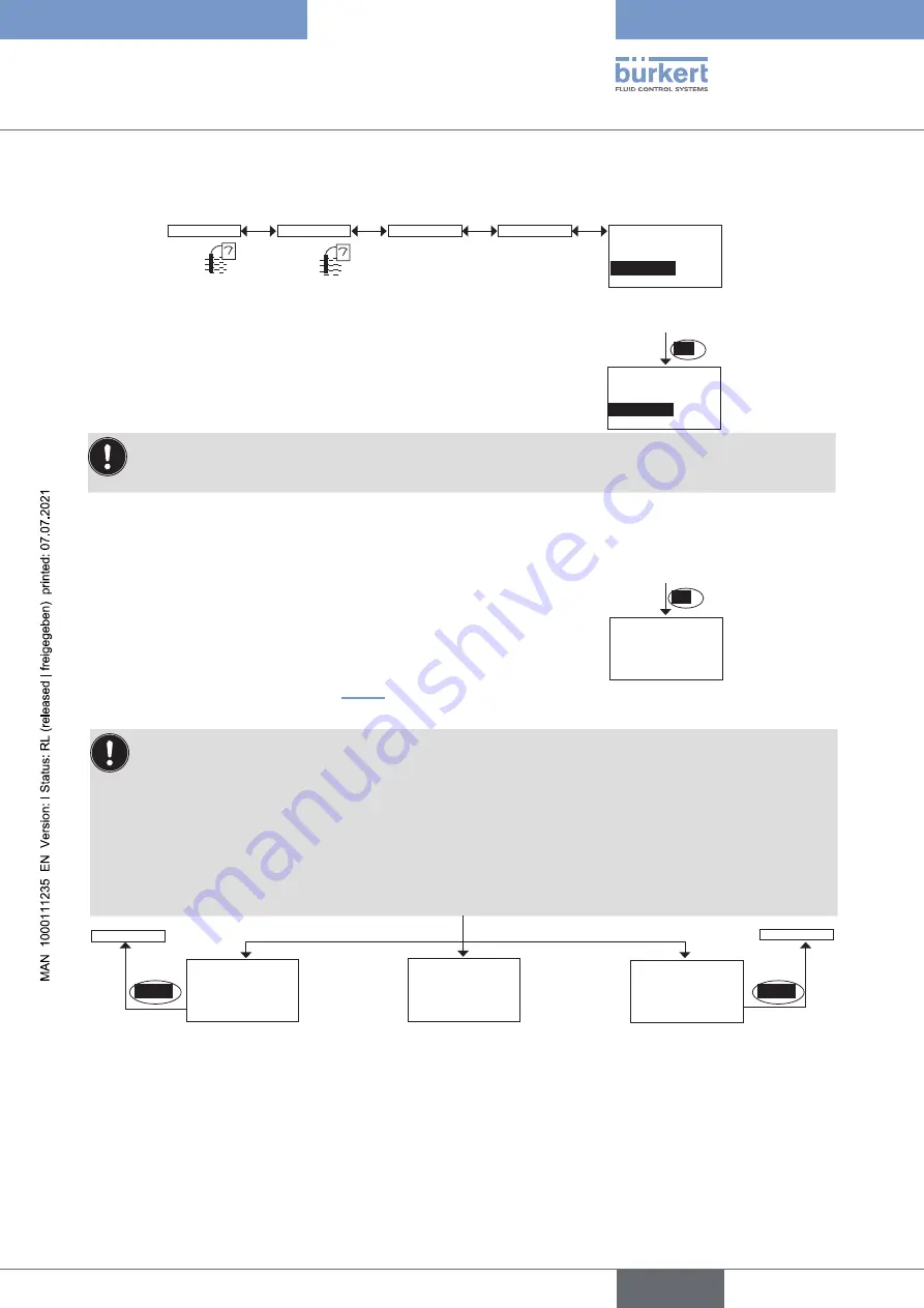
Define the temperature compensation graph specific to your process (“teach special” function in 
the”probe” menu)


Enter the value for the start of the temperature range for which 
the compensation graph must be determined.


Enter the value of the end of the temperature range for which 
the compensation graph must be determined.


Before confirming to begin the procedure, check that the fluid 
temperature is below 25 °C and T–.

OK

The message “Error: current temp. is too high” 
is displayed if, at the beginning of the Teach-
In procedure, the fluid temperature is higher 
than 25 °C or than T–. 

If the Hold mode is deactivated (chpt. 9.12.1), the device determines the compensation graph with 10 points and 
displays alternately the measured solution conductivity and the measured solution temperature.

•  During measurement, the fluid temperature must pass 25 °C.

•  Immerse the sensor in the solution and progressively reheat:


- from T– to T+ if T– < 25 °C < T+


- from 25 °C to T+ if 25 °C < T– < T+


- from T– to 25 °C if T– < T+ < 25 °C

•  The rise in temperature must be slow because of the inertia of the temperature sensor.

•  Avoid the formation of bubbles on the conductivity sensor.

The fluid temperature range (T–; T+) must be entered in such a way that the difference between T– and 
T+ is greater than 8 °C. The message "Error: Temp span at least 8 °C" is displayed if the difference 
between the range start and end values is less than 8 °C.

The message "Error: Temp 
span at least 8 °C" is displayed 
if the difference between the 
range start and end values is 
less than 8 °C.

BACK

Calib

Sensor

Teach special

Probe

At the end of processing, 
you are requested to save 
the calculated graph or not.

Cal. Result
Save: Yes/No

“Error: current 
temp. is too 
high”

Probe

Start temp

+40.00 °C

Stop temp

+55.00 °C

OK

Processing...

1.234 mS

"Error: temp 
span at least 
8 °C"

BACK

Probe

English

Type 8222 ELEMENT

Summary of Contents for 8222 ELEMENT NEUTRINO

Page 1: ...Operating Instructions Bedienungsanleitung Manuel d utilisation Type 8222 ELEMENT Conductivity meter Leitf higkeits Messger t Conductivim tre...

Page 2: ...rve the right to make technical changes without notice Technische nderungen vorbehalten Sous r serve de modifications techniques B rkert SAS 2008 2021 Operating Instructions 2106 6_EU ML 00560330 Orig...

Page 3: ...10 5 2 Construction of the 8222 10 5 3 Conductivity sensor 10 5 4 Type label 11 6 Technical data 12 6 1 Conditions of use 12 6 2 Conformity to standards and directives 12 6 2 1 Conformity to the Pres...

Page 4: ...tions 35 9 5 Entering a numerical value example 35 9 6 Browsing in a menu example 35 9 7 Knowing the display 36 9 7 1 Knowing the icons and LEDs 36 9 7 2 Knowing the display at the power up of the dev...

Page 5: ...g the Diagnostic menu access code 56 9 13 2 Monitoring the fluid conductivity 56 9 13 3 Monitoring the polarisation slope 57 9 13 4 Monitoring the fluid temperature 58 9 14 Knowing the Test menu 59 9...

Page 6: ...ns refers to the Type 8222 ELEMENT conductivity meter 1 2 Validity of the Operating Instructions The Operating Instructions are valid for the Type 8222 ELEMENT conductivity meter version V2 Mention V2...

Page 7: ...ences that may arise during instal lation use and maintenance of the device The operating company is responsible for the respect of the local safety regulations including staff safety Risk of injury d...

Page 8: ...Do not subject the device to mechanical stress Do not make any modifications to the device Prevent any unintentional power supply switch on Only qualified and skilled staff may carry out the installa...

Page 9: ...sales offices are available on the internet at country burkert com 4 2 Warranty conditions The condition governing the legal warranty is the conforming use of the device in observance of the operating...

Page 10: ...ory see chpt 11 One device variant of the device with 2 transistor outputs and a 4 20 mA output operates on a 2 wire system and requires a power supply of 14 36 V DC For such a device variant electric...

Page 11: ...bel of a Type 8222 ELEMENT device is valid for a device without conductivity sensor 5 Manufacturing code 6 Pin assignment of the electrical connection 7 Certification 8 Article number 9 Serial number...

Page 12: ...which verify conformity with the EU directives can be found on the EU type examination certificate and or the EU declaration of conformity if applicable 6 2 1 Conformity to the Pressure Equipment Dire...

Page 13: ...e 4 Paragraph 1 a ii PS 1000 bar 6 2 2 UL certification The devices with variable key PU01 or PU02 are UL certified devices and comply also with the following standards UL 61010 1 CAN CSA C22 2 n 6101...

Page 14: ...ing lid PC Housing lid seal silicone Display module PC PBT M12 male connector M12 female connector nickel plated brass stainless steel on request Support plate of the M12 male connector or M12 female...

Page 15: ...surement Measurement range 0 05 S cm 10 mS cm Resolution 1 nS cm Measurement deviation 3 of the measured value Recommended min divergence of the conductivity range associated to the 4 20 mA signal 2 o...

Page 16: ...5 14 13 12 11 10 9 8 7 6 5 4 3 2 1 0 0 20 40 60 T C P bar PVC PP 20 232 217 6 203 188 6 174 159 6 145 130 6 116 101 6 87 72 5 58 43 5 29 14 0 P psi Metal P Fluid pressure T Fluid temperature Fig 4 Dep...

Page 17: ...ith loads on the transistors 1 A max Power consumption 40 W max Protection against polarity reversal yes Protection against voltage spikes yes Transistor output polarized type NPN or PNP Through wirin...

Page 18: ...6 8 Data of connectors and cables Number of fixed connectors Type of connector 1 male M12 fixed connector 5 pin female M12 connector not supplied For the M12 connector with article number 917116 use...

Page 19: ...e housing lid Notice The tightness of the device is not guaranteed when the housing lid is removed Prevent the projection of liquid inside the housing The device may be damaged if a metal component co...

Page 20: ...display module Notice The tightness of the device is not guaranteed when the housing lid is removed Prevent the projection of liquid inside the housing The device may be damaged if a metal component c...

Page 21: ...ousing lid if necessary Refer to chpt 7 2 Turn the module by ca 20 counterclockwise Once unlocked the display module is raised slightly by the spring action Remove the display module from its housing...

Page 22: ...e the dependency between the fluid temperature and the fluid pressure Risk of burns due to high fluid temperatures Use safety gloves to handle the device Before opening the pipe stop the circulation o...

Page 23: ...the fluid Respect the prevailing regulations on accident prevention and safety relating to the use of dangerous fluids The device is inserted into a fitting installed on the pipe Select an appropriate...

Page 24: ...lace the seal if necessary Carefully insert the device into the fitting Position the device in such a way that the markings located on either side of the electronics box are parallel to the pipe Tight...

Page 25: ...o chpt 8 3 2 Protect the power supply of the device with a 100 mA time delay fuse and a switch Protect the power supply of each transistor output with a 750 mA fuse Once the device is wired set the HW...

Page 26: ...less grounding of the shield of the power supply cable Refer to Fig 13 and Fig 14 If the device is installed on plastic pipes earth together the metallic equipment such as pumps or valves that is as c...

Page 27: ...n yellow or grey 14 36 V DC 1 2 3 4 Load 1 solenoid valve for instance Load 2 solenoid valve for instance Power supply white blue black brown green yellow or grey Fig 16 NPN wiring of both transistor...

Page 28: ...Load 1 4 20 mA input at external device brown green yellow or grey blue white black Power supply Fig 19 NPN wiring of both transistor outputs and wiring of the current output in sinking mode software...

Page 29: ...order to ease wiring of the load to the female fixed connector Pin of the M12 female cable available as an accessory article number 438680 Colour of the wire 1 brown 2 white 3 blue 4 black 5 green ye...

Page 30: ...external device brown blue green yellow or grey Second 4 20 mA input at external device black brown black Fig 24 Wiring of both current outputs in sinking mode software setting NPN sink see chpt 9 11...

Page 31: ...sinking mode on a device variant with 2 fixed connectors software setting NPN sink see chpt 9 11 8 12 36 V DC 1 2 3 4 3 2 1 4 Load 1 1st 4 20 mA input at external device brown green yel low or grey b...

Page 32: ...e start up calibrate the conductivity sensor Refer to chpt 9 12 4 Before start up make sure that the staff in charge have read and fully understood the contents of the Operat ing Instructions In parti...

Page 33: ...Diagnostic see chpt 9 13 Test see chpt 9 14 Info see chpt 9 15 9 3 Using the navigation button Symbolised by in these Operating Instructions Symbolised by in these Operating Instructions Symbolised b...

Page 34: ...t the highlighted function browse in the dynamic functions bar MEAS BACK ABORT OK YES NO next function previous function confirm the highlighted dynamic function modify a numerical value increment the...

Page 35: ...the digit at the extreme right of the numerical value with then move the decimal point with Modify each digit of the numerical value using to increase the digit selected to decrease the digit selecte...

Page 36: ...under the display module these LEDs can only be seen if the device has no display module Icon Meaning and alternatives Sensor in good condition fluid conductivity and fluid temperature within the set...

Page 37: ...1 423 mS cm TempC 55 C CondS 1 423mS 18 3 mA AC1 7 5 mA AC2 A 1 1 1 First view of the Process level Zoom on the value in the first line Zoom on the value in the second line AC1 18 3 mA AC2 7 5 mA A D...

Page 38: ...s is when the device is be ing parame tered Param 2s Calib This is when the device is be ing parame tered Info This is when the device is be ing parame tered Diagnostic Test Any display of the Process...

Page 39: ...m Line1 Line2 Filter None Fast Slow Enabled Line1 Line2 PVar Reset Yes No Disabled Downl Yes No Upload Yes No Contrast xx Backlight xx CondR TempC TempF S cm C Unit mS cm F CondS TDSppm Min Max Enable...

Page 40: ...al closed INPUT Low INPUT High INPUT CondS TDSppm CondR TempC TempF Outputs HWMode sink NPN source PNP PVar Mode Hysteresis Window Sensor This is when the device is be ing parame tered Calib System Ho...

Page 41: ...arization Activate Yes No READ Warn hi INPUT Err hi INPUT Temperature Temperature Activate Yes No READ Warn lo INPUT Err hi INPUT Err lo INPUT Warn hi INPUT Calib Sensor Probe Teach special Cell cst T...

Page 42: ...9 to access the Parameters menu This function is only possible with a display module with software version V2 On the device check the software version in the menu Info Software Main The software versi...

Page 43: ...calibrations set in the menu Calib Sensor Probe Calib interval the access codes to the menus DOWNLOAD transfer the data previously uploaded into the display module using the UPLOAD function The parame...

Page 44: ...9 9 to access the Parameters menu The following data can be restored to their default values user set data of the PARAM menu except the date the time the contrast and brightness levels for the displa...

Page 45: ...ndR If PVar CondR MW cm If PVar CondR ppm If PVar TDSppm Display This is when the device is be ing parame tered Param This is when the device is be ing parame tered PVAR choose the process value to be...

Page 46: ...ured values are displayed in the Process level UNIT choose the preferred unit in which the lowest and highest measured values are displayed 9 11 7 Setting the display contrast and brightness See chpt...

Page 47: ...or outputs in PNP See chpt 8 3 Wiring 9 11 9 Setting the parameters of the current outputs See chpt 9 9 to access the Parameters menu The 2nd current output AC2 is only available on a device variant w...

Page 48: ...0 mA for each current output FILTER choose the level of damping for the fluctuations of the current value for each current output Three damping levels are proposed slow fast or none The damping for th...

Page 49: ...ut is linked to the warning event the transistor switches as soon as such an event is generated by the device See also chpt 10 3 Solving a problem MODE choose the operating hysteresis or window for tr...

Page 50: ...nu This menu is used to deactivate the temperature compensation choice none or choose the type of temperature compensation to determine the conductivity of the fluid according to a linear percentage c...

Page 51: ...n coefficient a according to a temperature range DT and the associated conductivity range Dc 25 25 T C T T T 25 T x 1 9 12 Knowing the Calibration menu 9 12 1 Activating deactivating the Hold function...

Page 52: ...hat the Hold mode is disabled Refer to chpt 9 12 1 On a device variant with a single M12 fixed connector and if the power supply is lower than 16 V DC before adjusting the current output make sure tha...

Page 53: ...is input does not update the last calibration date Last cal date function of the CALIB INTERVAL sub menu CELL CST TDS enter the TDS factor suited to your process The TDS factor allows for calculating...

Page 54: ...message Error out of range signals that the cell constant is out of the authorized range 0 008 or 12 this may be due to either a mistake made when entering the conductivity or the conductivity sensor...

Page 55: ...easurement the fluid temperature must pass 25 C Immerse the sensor in the solution and progressively reheat from T to T if T 25 C T from 25 C to T if 25 C T T from T to 25 C if T T 25 C The rise in te...

Page 56: ...See chpt 9 9 to access the Diagnostic menu The function allows for monitoring the fluid conductivity and configure the behaviour of the device if the param etered ranges are exceeded A malfunction in...

Page 57: ...nt is generated WARN LO enter the fluid conductivity value below which a warning event is generated ERR HI enter the fluid conductivity value above which an error event is generated ERR LO enter the f...

Page 58: ...above which a warning event is generated ERR HI enter the polarisation slope value above which an error event is generated 9 13 4 Monitoring the fluid temperature See chpt 9 9 to access the Diagnostic...

Page 59: ...puts See chpt 9 11 9 function Output AC1 or Output AC2 See also chpt 10 3 Solving a problem ACTIVATE choose whether or not to activate monitoring of the fluid temperature TEMPERATURE read the fluid te...

Page 60: ...ing correctly by selecting the status of the transistor ON or OFF then OK TR2 check that transistor output 2 is working correctly by selecting the status of the transistor ON or OFF then OK 9 14 3 Che...

Page 61: ...or See also chpt 10 3 Solving a problem 9 15 2 Reading the software versions See chpt 9 9 to access the Info menu Info Software Main Sensor READ READ The function allows for reading the software versi...

Page 62: ...lation stop the circulation of fluid cut off the pressure and drain the pipe Before any intervention in the installation make sure that there is no pressure in the pipe Observe the dependency between...

Page 63: ...ase feel free to contact your B rkert supplier for any additional information 10 3 Solving a problem Red LED Current output Transistor output Icon Message displayed in the Info menu Possible cause Rec...

Page 64: ...eturn the device to B rkert ON 22 mA depending on thresholds ERR TR EE Fact Read Parameter reading error Switch the power supply off then on again if the error persists set the device back to the defa...

Page 65: ...The message is displayed if the monitoring of the fluid conductivity has been activated depending on the set thresholds ERR LO and ERR HI see chpt 9 13 2 Go into the Sensor function of the Diagnostic...

Page 66: ...RR LO and ERR HI see chpt 9 13 4 Go into the Sensor function of the Diagnostic menu to read the measured fluid temperature chpt 9 13 4 If necessary check whether the built in Pt1000 is working correct...

Page 67: ...pt 9 13 3 If necessary clean and or recalibrate the conductivity sensor OFF 4 20 mA Switched 2 W Temperature The fluid temperature is out of range The message is displayed if the monitoring of the flu...

Page 68: ...d with 1 silicone seal 560948 Set with 2 transparent housing lids with seals 1 screw housing lid with 1 EPDM seal 1 quarter turn closing housing lid with 1 silicone seal 561843 Calibration solution 30...

Page 69: ...e range Protect the electrical interfaces using protective plugs 13 Storage Notice Poor storage can damage the device Store the device in a dry place away from dust Storage temperature of the device 1...

Page 70: ...70 English Type 8222 ELEMENT...

Page 71: ......

Page 72: ...www burkert com...

Reviews: