background image

30

Maintenanceandtroubleshooting

Type 8228

10  mAinTenAnce AnD 

TroubleshooTinG

10.1  safety instructions

risk of injury due to electrical voltage.


Shut down the electrical power for all the conductors and iso-
late it before carrying out work on the system.


If a 12...36 V DC powered version is installed either in a wet 
environment or outdoors, all the electrical voltages must be of 
max. 35 V DC.


All equipment connected to the device shall be double insu-
lated with respect to the mains according to the standard 
IEC 61010-1:2010.


Observe all applicable accident protection and safety regula-
tions for electrical equipment.

risk of injury due to high pressure in the installation.


Stop the circulation of fluid, cut off the pressure and drain the 
pipe before loosening the process connections.

risk of burns due to high fluid temperatures.


Use safety gloves to handle the device.


Stop the circulation of fluid and drain the pipe before loosening 
the process connections.

risk of injury due to the nature of the fluid.


Respect the prevailing regulations on accident prevention and 
safety relating to the use of dangerous fluids.

Warning

risk of injury due to non-conforming maintenance.


Maintenance must only be carried out by qualified and skilled 
staff with the appropriate tools.


Ensure that the restart of the installation is controlled after any 
interventions.


If there is a problem, see the Operating Instructions at: 

www.

burkert.com


11  pAckAGinG, TrAnsporT

notiCe


damage due to transport

Transport may damage an insufficiently protected device.


Transport the device in shock-resistant packaging and away 
from humidity and dirt.


Do not expose the device to temperatures that may exceed the 
admissible storage temperature range.


Protect the electrical interfaces using protective plugs.

English

Summary of Contents for 8228 ELEMENT

Page 1: ...Quickstart English Deutsch Français Type 8228 Inductive conductivity meter Induktives Leitfähigkeits Messgerät Conductimètre inductif ...

Page 2: ...e reserve the right to make technical changes without notice Technische Änderungen vorbehalten Sous réserve de modifications techniques Bürkert SAS 2014 2018 Quickstart 1809 04_EU ML 00567368 ORIGINAL_FR ...

Page 3: ...res 13 7 Assembly 14 7 1 Safety instructions 14 7 2 Mounting the display module 14 8 Installation and wiring 15 8 1 Safety instructions 15 8 2 Installing a 8228 with a G2 process connection in the pipe 16 8 3 Installing a 8228 with a 2 clamp process connection in the pipe 17 8 4 Wiring the device 18 9 Operating and commissioning 23 9 1 Safety instructions 23 9 2 Using the navigation button 24 9 3 ...

Page 4: ...A detailed description of the device can be found in the related Operating Instructions The Operating Instructions for the device can be found on the Internet at www burkert com 1 1 Definition of the word device The word device used within this quickstart refers to the Type 8228 ELEMENT conductivity meter 1 2 Validity of this quickstart This quickstart is valid for the Type 8228 ELEMENT conductivi...

Page 5: ...ment The Type 8228 ELEMENT conductivity meter is intended solely for the measurement of the conductivity Use the device in compliance with the characteristics and commissioning and use conditions specified in the contractual documents and in the Operating Instructions Never use the device for security applications Protect the device against electromagnetic interference ultra violet rays and when i...

Page 6: ...ain the pipe before loosening the process connections Risk of burns due to high fluid temperatures Use safety gloves to handle the device Stop the circulation of fluid and drain the pipe before loosening the process connections Risk of injury due to the nature of the fluid Respect the prevailing regulations on accident prevention and safety relating to the use of dangerous fluids Various dangerous...

Page 7: ...destroyed or disabled as soon as they are activated To minimise or even avoid any damage caused by an elec trostatic discharge take all the precautions described in the EN 61340 5 1 norm Also make sure that you do not touch any of the live electrical components 4 General information 4 1 Manufacturer s address and international contacts To contact the manufacturer of the device use following addres...

Page 8: ... of the device example 1 Supply voltage 2 Type of the device 3 Measurable variable 4 Version 5 Max power consumption 6 Max current available at the transistor output s 7 Conductivity measuring range 8 Fluid temperature range 9 Pin assignment of the M12 fixed connector s 10 Conformity marking 11 Article number 12 Serial number 13 Warning Before using the device take into account the tech nical spec...

Page 9: ... to the Pressure Equipment Directive Make sure the device materials are compatible with the fluid Make sure the pipe DN and PN are adapted for the device The device conforms to Article 4 Paragraph 1 of the Pressure Equipment Directive 2014 68 EU under the following conditions Device used on a pipe PS maximum admissible pressure DN nominal diameter of the pipe Type of fluid Conditions Fluid group 1...

Page 10: ...d the material the S020 fitting used is made of see Fig 2 8228 with conductivity sensor in PVDF 15 100 C 8228 with conductivity sensor in PP 0 80 C 8228 with conductivity sensor in PEEK 15 130 C Fluid pressure The fluid pressure may be restricted by the fluid temperature the material the conductivity sensor holder is made of and the material the S020 fitting used is made of see Fig 2 8228 with con...

Page 11: ...rial Box seals stainless steel 316L 1 4404 PPS EPDM Cover seal PC silicone Display module PC PBT M12 fixed connector nickel plated brass stainless steel on request 2 clamp process con nection stainless steel Part Material Fixed connector holder stainless steel 316L Screws stainless steel Nut PC Conductivity sensor holder seal in contact with the fluid PVDF FKM PP FKM PEEK FKM Version with 2 clamp ...

Page 12: ...lectrical data Power supply 12 36 V DC Connection to main supply per manent through external SELV and LPS power supply filtered and regulated oscillation rate 10 Power source not supplied Limited power source according to UL EN 60950 1 standards or limited energy circuit according to UL EN 61010 1 9 4 Current consumption without the consumption of the current outputs and the transistor outputs max...

Page 13: ...f connection 3 wire max loop impedance 1100 W at 36 V DC 610 W at 24 V DC 100 W at 12 V DC Responsetime 10 90 150 ms default value 6 7 Data of the connectors and wires Number of fixed connectors Type of connector 1 male M12 fixed connector 5 pin M12 female connector not supplied For the female M12 connector with article number 917116 use a shielded cable diameter 3 6 5 mm wire cross section max 0 ...

Page 14: ...arting of the installation Avoid unintentional activation of the installation Guarantee a set or controlled restarting of the process subse quent to any intervention on the device 7 2 Mounting the display module 20 Remove the cover Set the display module at an angle of about 20 in relation to the desired position a b c d The module can be mounted in 4 different posi tions at 90 intervals Fully pus...

Page 15: ... Respect the prevailing regulations on accident prevention and safety relating to the use of dangerous fluids Warning Risk of injury due to non conforming installation The electrical and fluid installation can only be carried out by qualified and skilled staff with the appropriate tools Install appropriate safety devices correctly rated fuse and or circuit breaker Respect the assembly instructions...

Page 16: ...le see chap 7 2 to calibrate the conduc tivity sensor and to parameter the device Calibrate the zero point of conductivity see chap 9 7 Install the device in the fitting as shown in Fig 7 1 2 3 4 5 Make sure the seal mark 2 is on the conductivity sensor Make sure the material of the seal is compatible with the fluid to be measured Put the nut mark 5 on the fitting Put the snap ring mark 3 into the...

Page 17: ...the fitting used not delivered Fig 8 shows an example for the fitting mark 5 Mount the fitting on the pipe obeying the instructions of the operating instructions of the fitting used Fit the display module see chap 7 2 to calibrate the conduc tivity sensor and to parameter the device Calibrate the conductivity sensor see chap 9 7 Install the device in the fitting as shown in Fig 8 3 1 2 5 4 Select ...

Page 18: ...ature limit of 80 C minimum Do not install the connection cables near high voltage or high frequency cables If this cannot be avoided observe a min distance of 30 cm Protect the power supply of the device with a 100 mA time delay fuse and a switch Protect the power supply of each transistor output with a 750 mA fuse 8 4 1 Assembling the male or female fixed connector available as an accessory 4 3 ...

Page 19: ...dif ferent earthes Observe faultless earthing of the shield of the power supply cable at both ends If the device is installed on plastic pipes earth together the metallic instruments such as pumps or valves that are as close as possible to the device 12 36 V DC Power supply Metal pipe Fig 10 Equipotentiality skeleton diagram with pipes in metal Devices such as valves pumps 12 36 V DC Power supply ...

Page 20: ... single M12 fixed connector Pin of the M12 female cable available as an accessory article number 438680 Colour of the wire 1 brown 2 white 3 blue 4 black 5 grey 12 36 V DC 1 2 3 4 Load brown grey black white blue Power supply 4 20 mA input at exter nal instrument Fig 13 NPN wiring of the transistor output and and wiring in sinking mode of the current output of a version with 1 fixed connector para...

Page 21: ...cing mode of the current output of a version with 1 fixed connector parameter setting PNP source 8 4 4 Wiring a version with 2 M12 fixed connectors Male fixed connector 1 2 3 4 Transistor output 1 TR1 Current output 1 AC1 0 V V 12 36 V DC Female fixed connector 1 2 3 4 V 12 36 V DC Transistor output 2 TR2 Current output 2 AC2 0 V Fig 15 Pin assignment of the male and female M12 fixed connectors En...

Page 22: ...M12 cables available as accessories article number 438680 respec tively 559177 Colour of the wire 1 brown 2 white 3 blue 4 black 5 grey 12 36 V DC 1 2 3 4 3 2 1 4 Load 1 1st 4 20 mA input at external instru ment brown grey black white blue Power supply 2nd 4 20 mA input at external instrument Load 2 brown black white Fig 16 NPN wiring of both transistor outputs and wiring of both current outputs i...

Page 23: ...e 9 Operating and commissioning The settings can only be done on a device with a display module Do not remove the display module while making the set tings on the device 9 1 Safety instructions Warning Risk of injury due to non conforming operating Non conforming operating could lead to injuries and damage the device and its surroundings The operators in charge of operating must have read and unde...

Page 24: ... charge have read and fully understood the contents of this quickstart In particular observe the safety recommendations and intended use The device the installation must only be commissioned by suit ably trained staff Set the correction factor of the fitting used see chap 9 8 9 2 Using the navigation button Symbolised by in this quickstart Symbolised by in this quickstart Symbolised by in this qui...

Page 25: ...elect the highlighted function You want to Press browse in the dynamic functions bar MEAS BACK ABORT OK YES NO next function previous function confirm the highlighted dynamic function modify a numerical value increment the figure selected decrement the figure selected select the previous figure select the next figure allocate the or sign to the numerical value to the extreme left of the numerical ...

Page 26: ... LOCK CondS 0 000 µS cm TempC 23 8 C ERR Red LED shows an error not used Yellow LED shows that transistor 1 is switched Yellow LED shows that transistor 2 is switched Fig 19 PositionofthesymbolsanddescriptionoftheLEDsonthedisplaymodule Red LED shows an error Yellow LED shows that transistor 2 is switched Green LED shows that the device is energized Yellow LED shows that transistor 1 is switched Fi...

Page 27: ...e Con figuration level When the device is powered up or the display module mounted on the electronic module the display indicates the software version of the display module then it shows the first screen of the Process level To browse in the Process level see chap 9 2 The Configuration level has 5 menus Param Calib Diag nostic Test Info To access the Configuration level and to browse in the menus ...

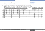
Page 28: ...d Put the cleaned and dried conductivity sensor in contact with the ambient air Choose Yes Save or not the calibration result by choosing Yes or No 9 8 Entering the correction factor of the fitting used The correction factor depends on the shape the material and the diameter of the fitting used The following table gives the correction factors of the fittings S020 From the Process level access the ...

Page 29: ...s Fittings with internal or external thread connections or fittings with weld end connections Measurement chamber Welding sockets or fusion spigots PVDF PP PVC Brass Stainless steel Stainless steel PVDF PP 32 1 08 1 08 1 08 0 99 0 99 32 1 08 1 08 1 08 0 99 0 99 0 99 40 1 04 1 04 1 04 0 99 0 99 0 99 50 1 02 1 02 1 02 0 99 0 99 0 99 0 99 65 0 99 1 02 1 02 80 0 99 1 02 1 02 100 1 00 1 02 1 02 100 1 0...

Page 30: ...sk of burns due to high fluid temperatures Use safety gloves to handle the device Stop the circulation of fluid and drain the pipe before loosening the process connections Risk of injury due to the nature of the fluid Respect the prevailing regulations on accident prevention and safety relating to the use of dangerous fluids Warning Risk of injury due to non conforming maintenance Maintenance must...

Page 31: ...st Storage temperature of the device 10 60 C 13 Disposal of the device Dispose of the device and its packaging in an environmentally friendly way Notice Damage to the environment caused by parts contaminated by the fluid Comply with the national and or local regulations which concern the area of waste disposal English ...

Page 32: ...www burkert com ...

Reviews: