130
Auxiliary functions
Type 8792, 8793 REV.2
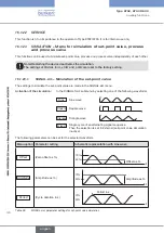
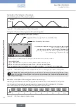
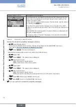
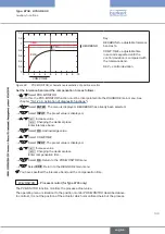
Explanation of the histogram in the example
Sinusoidal progression of the actuator position:
Position
Time [t]
100%
0%
Figure 43:
Sinusoidal progression of the actuator position
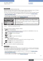
Histogram of the sinusoidal progression of the actuator position:
STOP
CLEAR
POS–Class
10
:
34
:
00
10023 c
M
30
Duration of histogram recording
Largest dwell time density which occurred (tallest bar)
Path covered by the actuator
The histogram indicates how long the actuator has stopped
in the particular position class.
The figure in the middle of the histogram indicates what
percentage of time the actuator has spent in the position
class with the largest dwell time density.
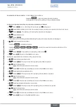
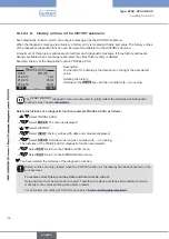
Conclusions to be drawn from the histogram about the behavior of the actuator:
The actuator spent
approx. 30% of its time in position class 1 (0-10% of the total stroke) and
approx. 30% of its time in position class 10 (90 - 100% of the total stroke).
For the remaining time the actuator was in a position between 11% and 89% of the total stroke.
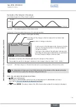
Figure 44:
POS-Class; histogram of the dwell time density for sinusoidal progression of the actuator position
The distribution of the histogram allows conclusions to be drawn about the design of the control
valve. For example, if the actuator is in the lower stroke range only, the valve has probably been
designed too large.
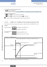
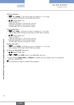
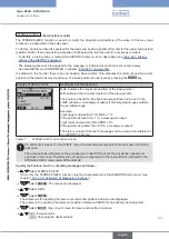
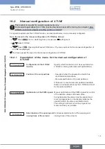
DIR-Class -
Description of the histogram of the movement range
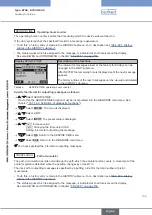
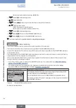
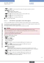
The histogram indicates the movement ranges of the actuator between two direction reversal points.
For this purpose the movement range between two changes in direction is divided into 10 classes.
The current position of one of the 10 classes is assigned to each scan time.
0 - 10
%
11
- 20%
21
- 30%
31
- 40%
41
- 50%
51
- 60%
61
- 70%
71
- 80%
81
- 90%
91
- 100%
Class
1
2
3
4
5
6
7
8
9
10
Figure 45:
DIR-Class; change in direction classes
english
Summary of Contents for 8792
Page 196: ...www burkert com ...

