5
note!
Electrostatic sensitive components / modules!
The device contains electronic components which react sensitively to
electrostatic discharge (ESD). Contact with electrostatically charged
persons or objects is hazardous to these components. In the worst case
scenario, they will be destroyed immediately or will fail after start-up.
• Observe the requirements in accordance with EN 61340-5-1 and
5-2 to minimise or avoid the possibility of damage caused by sudden
electrostatic discharge!
• Do not touch live electronic components!
4
General informaTion
4.1 Warranty
The warranty is only valid if the device is used as authorized in accordance
with the specified application conditions.
4.2 information on the internet
Operating instructions and data sheet for Type 8605 can be found on
the Internet at:
www.burkert.com
5
ProducT descriPTion
5.1 field of application
The Control Electronics, Type 8605, is designed for continuous operation
in industrial environments, in particular in the fields of open-loop and
closed-loop control engineering.
5.2 General description
The Digital Control Electronics for Proportional Valves, Type 8605 (here-
inafter referred to as Control Electronics, Type 8605) Controls all Bürkert
proportional valves with a max. current in the range from 40 to 2000 mA.
It transforms an external standard signal into a pulse-width modulated
voltage signal (PWM) that is supplied to the solenoid coil of the propor-
tional valve.
A given value of the average coil current is thereby assigned to each
value of the input signal. The proportional opening of the valve can be
set via the coil current.
english
6
5.3 forms of the device
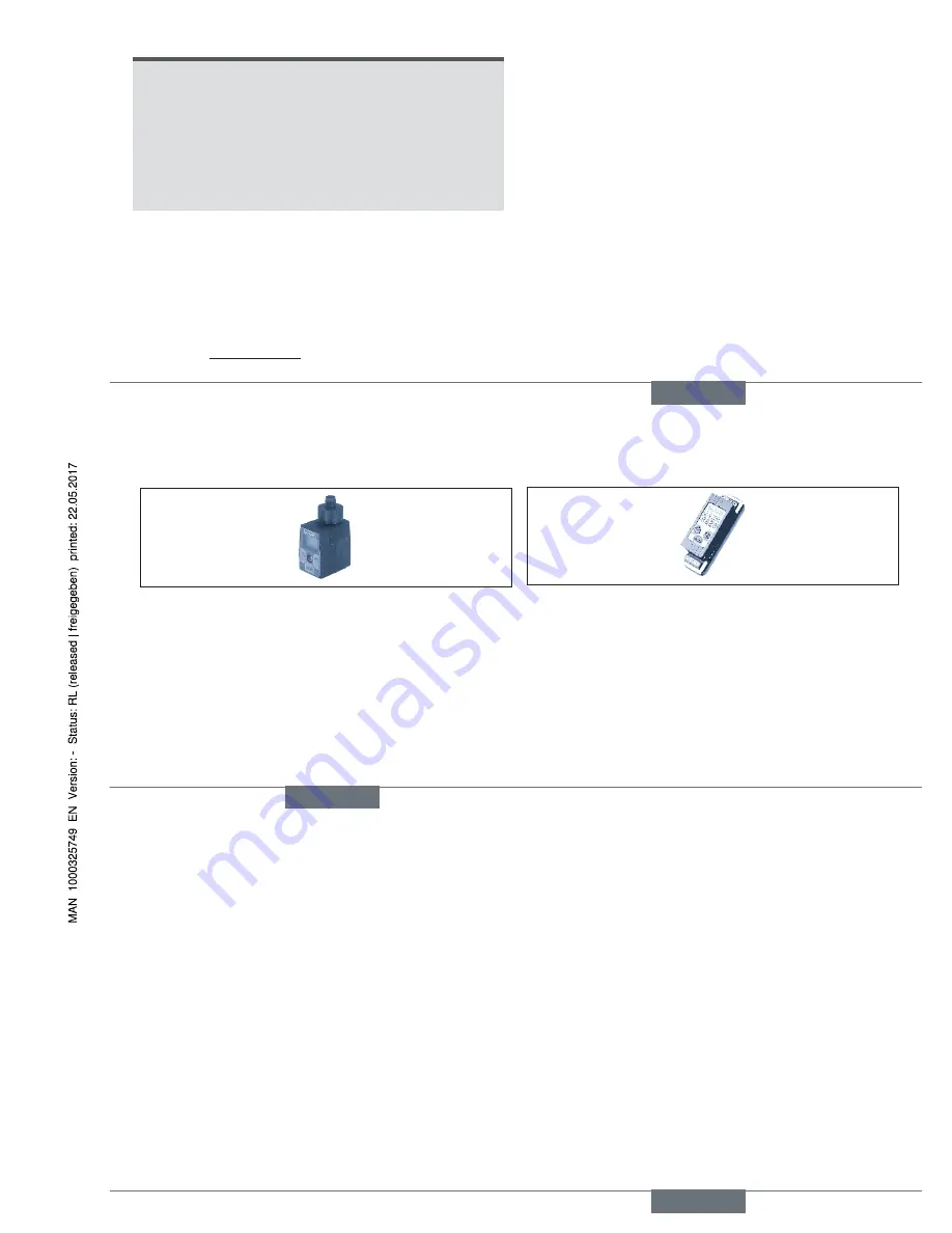
5.3.1 Type 8605 cable plug version
Fig. 1: Type 8605 Cable plug version
Plug-in version on valves with connector pattern A (e. g. types 2832,
2833, 2834, 2835, 2836, 2853, 2863, 2865, 2873, 2875, 6022,
6023, 6024, 6223).
The operating unit can be removed after the setting process. During
operation of the Control Electronics 8605 in cable plug version without
operating unit, the operating status is indicated by two LEDs.
Device variants:
• Variant 1 for valves with a max. current from 200 to 1000 mA
• Variant 2 for valves with a max. current from 500 to 2000 mA
5.3.2 Type 8605 din rail version
Fig. 2: Type 8605 DIN rail version
Separate electronics in housing for DIN rail mounting to DIN EN 50022.
This form is suitable for all proportional valves in the indicated current
range. The operating unit cannot be removed.
Device variants:
• Variant 1 for valves with a max. current from 40 to 220 mA
• Variant 2 for valves with a max. current from 200 to 1000 mA
• Variant 3 for valves with a max. current from 500 to 2000 mA
english
7
6
Technical daTa
6.1 operating conditions
Power supply
12...24 V DC ± 10%
Residual ripple 5 %
Power consumption
ca. 1 W
Output current
(on the valve)
max. 2 A
Operating temperature
-10 ... 60 ºC / 14 ...140 ºF
Interference resistance
to EN50082-2
Emission
to EN50081-2
Current range, depending
on the version for valves
40 ... 220 mA,
200 ... 1000 mA,
500 ... 2000 mA
Standard signal input
Voltage (0 ... 5, 0 ... 10 V)
input impedance > 20 k
W
Current (0 ...20, 4 ... 20 mA) input impedance < 200
W
Housing: DIN rail version
Degree of protection
IP40 (DIN EN 60529)
Materials
Polyamide / PBT
Dimensions
LxWxH: 97 x 27 x 57 mm
Housing: Cable plug version
Degree of protection
IP65 (DIN EN 60529)
Materials
Polyamide / PC
Dimensions
LxWxH: 70 x 32 x 42.5 mm
english


