16
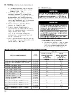
Table 4: Vent/Combustion air System Options
iV. Venting
A. General Guidelines (continued)
approved Direct
Vent System
Vent
Material
Orientation
Termination
Description
Figures
Component
Table
Part
Factory Standard
Two-Pipe,
CPVC/PVC Vent and
PVC
Air Intake
CPVC/PVC
Horizontal
Standard
(thru sidewall)
The system includes separate CPVC
vent pipe and PVC air intake pipe
terminating thru sidewall with individual
penetrations for the vent and air intake
piping and separate terminals (tees).
4 thru 9A,
9B, 10
5A
B.
Optional
Snorkel
(thru sidewall)
Same as above but separate snorkel
type terminals.
4 thru 7,
10, 11
5B
Optional
Vertical
Vertical
(thru roof)
The system includes separate CPVC
vent pipe and PVC air intake pipe
terminating thru roof with individual
penetrations for the vent and air intake
piping and separate vertical terminals.
4 thru 6, 10,
12, 13
5C
Available Optional
Two-Pipe, Rigid
Polypropylene
Vent
(or Flexible
Polypropylene Liner
for Vertical venting
only)
and Rigid
Polypropylene or PVC
Pipe Air Intake
Rigid
Polypropylene
(or Flexible
Polypropylene
Liner for vertical
Venting only)
Horizontal
Standard
(thru sidewall)
The system includes separate Rigid
Polypropylene vent pipe and Rigid
Polypropylene or PVC air intake pipe
terminating thru sidewall with individual
penetrations for the vent and air intake
piping and separate terminals (tees).
4 thru 9A,
9B, 10
9, 10
C.
Optional Snorkel
(thru sidewall)
Same as above but separate snorkel
type terminals.
4 thru 7,
10, 11
9, 10
Optional
Vertical
Vertical
(thru roof or
chimney/chase)
The system includes separate Flexible
Polypropylene vent liner and Rigid
Polypropylene vent pipe combination
for venting and Rigid Polypropylene or
PVC air intake pipe terminating thru roof
with individual penetrations for the vent
and air intake and individual vent /air
terminals.
12 thru 16
9, 10
Available Optional
Two-Pipe,
Stainless Steel Vent
and PVC/Galvanized
Steel Air Intake
Stainless Steel
Horizontal
Standard
(thru sidewall)
The system includes separate stainless
steel vent pipe and PVC/galvanized steel
air intake pipe terminating thru sidewall
with individual penetrations for the
vent and air intake piping and separate
terminals
9A, 9B,
16, 17
11A, 11B
D.
Optional Snorkel
(thru sidewall)
Same as above but separate snorkel
type terminals.
11, 16, 17
Vertical
Vertical (thru roof)
The system includes separate stainless
steel vent pipe and PVC/galvanized steel
air intake pipe terminating thru roof with
individual penetrations for the vent and
air intake piping and separate terminals.
12, 13, 17
Available Optional
Concentric, Inner
Polypropylene Vent and
Outer Steel Air Intake
Polypropylene
Horizontal
Horizontal
(Wall) Terminal
Concentric vent/air pipe terminates thru
sidewall.
18 thru 25
12, 13
E.
Vertical
Vertical (Roof)
Terminal
Concentric vent/air pipe terminates thru
roof.
18 thru 21,
26 thru 31
i.
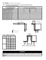
The centerlines between the vent and air
intake terminals must be spaced a minimum
of 12” apart. More than 12” spacing is
recommended.
ii.
If possible, locate air intake and vent
terminations on the same wall to prevent
nuisance shutdowns. However, boiler
may be installed with vertical venting and
sidewall combustion air inlet or vice versa
where installation conditions do not allow
for alternate arrangement.
iii.
The vent and air intake terminations may
be at varying heights when installed on
the same wall, but the height of the vent
termination should always be higher than
the air intake termination and within the
specified limit as shown in Figure 9B.
c. The bottom of the vent and air intake terminal
must be at least 12" (18" in Canada) above the
normal snow line. In no case should they be less
than 12" above grade level.
d. The bottom of the vent terminal must be at least
7 feet above a public walkway.
e. Do not install the vent terminal directly over
windows or doors.
f. The bottom of the vent terminal must be at least
3 feet above any forced air inlet located within
10 feet.
g. A clearance of at least 4 feet horizontally must
be maintained between the vent terminal and
gas meters, electric meters, regulators, and relief
equipment. Do not install vent terminal over this
equipment.
Summary of Contents for Apex APX399
Page 65: ...65 VIII Electrical continued Figure 43 Ladder Diagram ...
Page 66: ...66 VIII Electrical continued ...
Page 67: ...67 Figure 44 Wiring Connections Diagram VIII Electrical continued ...
Page 110: ...110 1P 3 1P 2 1P 1 XIII Repair Parts continued 1C 1D 1E ...
Page 116: ...116 XIII Repair Parts continued ...
Page 118: ...118 XIII Repair Parts continued ...
Page 129: ...129 SERVICE RECORD DATE SERVICE PERFORMED ...
Page 130: ...130 SERVICE RECORD DATE SERVICE PERFORMED ...


