73
G
.
Multiple Boiler Operating Information
1. Required Equipment and Setup
a. Header Sensor (P/N 101935-01 or 103104-01)
A header sensor must be installed and wired
to the Master Sequencer “enabled” Sage2.1
Controller. The header sensor is installed on the
common system piping and provides blended
temperature information to the Sequence Master.
Refer to piping diagram Figures 39A and 40A
for installation location and Figure 48 or 49 for
installation detail.
b.
RJ45 Splitters (P/N 103192-01)
RJ45 Splitters are required for installing
communications between three or more boilers.
When two boilers are connected the splitter is
not required.
c. Ethernet Cables
Ethernet cables are used to connect the boiler
network together. These are standard “straight
through” cables that can be purchased at
electrical distributors.
Alternately, the network can be wired together
by simply wiring terminal J3, Modbus 2,
terminals A, B and V- between each boiler.
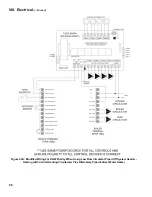
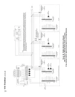
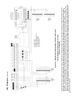
Refer to Figures 43 and 44 terminal J3 for wiring
location.
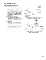
Figure 48: recommended Direct immersion
Header Sensor installation Detail
Figure 49: alternate “immersion” type Header
Sensor installation Detail
Viii. Electrical
(continued)
Summary of Contents for Apex APX399
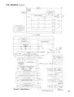
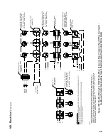
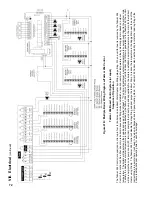
Page 65: ...65 VIII Electrical continued Figure 43 Ladder Diagram ...
Page 66: ...66 VIII Electrical continued ...
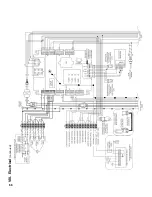
Page 67: ...67 Figure 44 Wiring Connections Diagram VIII Electrical continued ...
Page 110: ...110 1P 3 1P 2 1P 1 XIII Repair Parts continued 1C 1D 1E ...
Page 116: ...116 XIII Repair Parts continued ...
Page 118: ...118 XIII Repair Parts continued ...
Page 129: ...129 SERVICE RECORD DATE SERVICE PERFORMED ...
Page 130: ...130 SERVICE RECORD DATE SERVICE PERFORMED ...

