80
nOTiCE
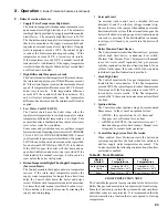
if the throttle is very far out of adjustment on the “rich” (counter-clockwise) side, the boiler burner may be
running at 0% Excess Air or even with air deficiency.
at 0% Excess air the CO
2
readings will be either 11.9% CO
2
for natural gas or 13.8% CO
2
for LP gas (O
2
will
be 0%) and CO level will be extremely high (well over 1000 PPM).
If the burner operates with air deficiency, the following phenomena may be observed:
% CO
2
will actually drop (% O
2
will increase) as the throttle is turned counterclockwise
% CO
2
will actually increase (% O
2
will drop) as the throttle is turned clockwise
If the boiler appears to operate with air deficiency, turn the throttle
clockwise to increase the amount of
Excess air to the burner.
as the throttle is turned clockwise, the CO
2
level will rise, eventually peaking @ 11.8% or 13.8%, depending
of the type of gas being used, before falling (conversely, O
2
level will drop to 0% before rising). after this
happens, continue turning the throttle clockwise, until CO
2
level drops (or O
2
level increases) to the values
shown in Table 24 or Table 26.
Warning
The pressure regulator (offset screw) has been factory set using precision instruments and must never
be adjusted in the field unnecessarily. The gas valve outlet pressure is the same for both natural gas and
propane. Make sure that all adjustments are made with the throttle, not the pressure regulator. attempting
to adjust the pressure regulator unnecessary, will result in damage to the gas valve and may cause property
damage, personal injury or loss of life.
iX. System Start-up
(continued)
Boiler Model
altitude range
0 - 5000 Ft.
5001 - 10000 Ft.
% CO
2
% O
2
range
CO, PPM
APX399
11.4 - 9.5
(High Fire)
11.4 - 9.1
(Low Fire)
3.5 - 6.5
(High Fire)
3.5 - 7.0
(Low Fire)
Less than
100 PPM
APX500
APX800
10.8 - 9.1
(High Fire)
10.8 - 9.1
(Low Fire)
4.5 -7.0
(High Fire)
4.5 - 7.0
(Low Fire)
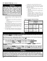
Table 26: Typical Combustion Settings,
LP gas
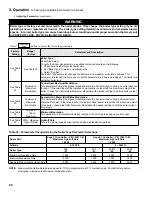
Warning
These instructions include a procedure for
adjusting the air-fuel mixture on this boiler.
This procedure requires a combustion analyzer
to measure the CO
2
(or Oxygen) and Carbon
Monoxide (CO) levels in flue gas. Adjusting the
air-fuel mixture without a proper combustion
analyzer could result in unreliable boiler operation,
personal injury, or death due to carbon monoxide
poisoning.
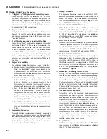
7. While the burner is at high fire adjust the throttle as
needed to obtain the CO
2
(or O
2
) settings shown in the
Table 26:
• To reduce the CO
2
(increase the O
2
) turn the throttle
clockwise
• To increase the CO
2
(reduce the O
2
) turn the throttle
counter-clockwise
Make adjustments in increments of 1/8 to 1/4 turn and
allow the boiler at least a minute to respond to each
adjustment before making another. In general, the CO
level will be at its lowest somewhere in the CO
2
range
shown in this table.
8. Verify that the gas inlet pressure is between the upper and
lower limits shown in Table 22 with all gas appliances
(including the converted boiler) both on and off.
9. A label sheet is provided with the boiler for conversions
from natural to LP gas. Once conversion is completed,
apply labels as follows:
• Apply the “Rating Plate Label” adjacent to the
rating plate.
• Apply the “Gas Valve Label” to a conspicuous area
on the gas valve.
• Apply the “Boiler Conversion Label” to a
conspicuous surface on, or adjacent to, the outer
boiler jacket. Fill in the date of the conversion and
the name and address of the company making the
conversion with a permanent marker.
Summary of Contents for Apex APX399
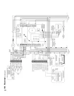
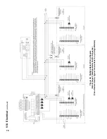
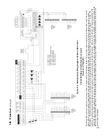
Page 65: ...65 VIII Electrical continued Figure 43 Ladder Diagram ...
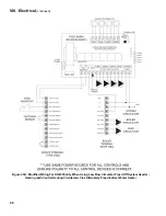
Page 66: ...66 VIII Electrical continued ...
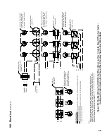
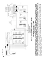
Page 67: ...67 Figure 44 Wiring Connections Diagram VIII Electrical continued ...
Page 110: ...110 1P 3 1P 2 1P 1 XIII Repair Parts continued 1C 1D 1E ...
Page 116: ...116 XIII Repair Parts continued ...
Page 118: ...118 XIII Repair Parts continued ...
Page 129: ...129 SERVICE RECORD DATE SERVICE PERFORMED ...
Page 130: ...130 SERVICE RECORD DATE SERVICE PERFORMED ...

