86
X. Operation
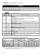
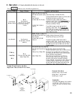
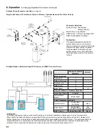
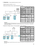
E. Boiler Sequence Of Operation (continued)
2.
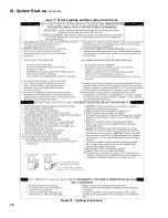
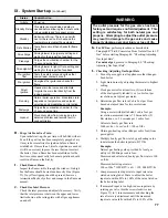
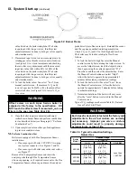
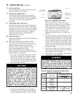
Using The Display
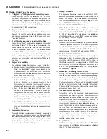
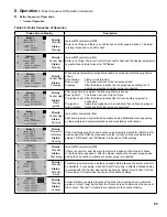
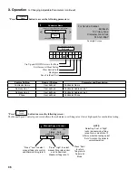
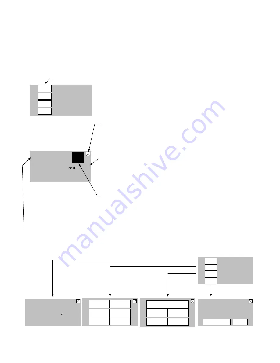
The Control includes a touch screen LCD display. The user monitors and adjusts boiler operation by selecting screen
navigation “buttons” and symbols. Navigation features are shown below.
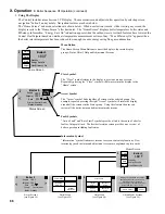
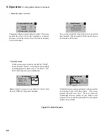
The “Home Screen” and menu selections are shown below. When no selection is made, while viewing any screen, the
display reverts to the “Home Screen” after 4 minutes. The “Home Screen” displays boiler temperature, boiler status and
Efficiency Information. “Energy Save On” indication appears when the outdoor reset or setback features have lowered the
Central Heat Setpoint based on outside air temperature measurement or time of day. “Max Efficiency On” appears when
the boiler return temperature has been reduced low enough to cause energy saving flue gas condensation.
180 F
Boiler 1
Energy Save On
Max Efficiency On
Standby
i
Status
Help
Adjust
Detail
Home Screen
Help Menu
(see Figure 60)
Detail Menu
(see Figure 55)
Status Screens
(see Figure 54)
Adjust Mode Screens
(see Figure 56)
Supply 180 F
180 F
Rate
0%
Status: Standby
Setpoint
Boiler 1
>
<
Priority:
Central Heat
i
Central Heat
Domestic
Hot Water
Outdoor
Reset Curve
Warning! Only Qualified Technicians
Should Adjust Controls, Contact Your
Qualified Heating Professional
Improper settings or service create risk of
property damage, injury, or death.
Service Contact
Adjust
Lockout
History
Service
Contract
Boiler Size
Setup
Sequencer
Setup
Active Faults
i
Supply
180 F
180 F
Rate
0%
Status: Standby
Setpoint
Boiler 1
>
<
Priority: Central Heat
i
Active
Fault
180 F
Boiler 1
Energy Save On
Max Efficiency On
Standby
i
Status
Help
Adjust
Detail
Home Screen
Status Screen
Menu Button
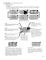
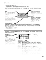
The Home Screen Menu Buttons connect the displays four main display
groups; Status, Detail, Help and Adjustment Screens.
Close Symbol
The “Close” symbol returns to the display to previous menu or screen.
Repeatedly pressing the “Close” symbol will always return the display to the
“Home” screen.
Arrow Symbol
The “Arrow” symbol links together all screens in the selected group. For
example, repeated pressing the right “Arrow” symbol will rotate the display
around all the screens in the Status group. Using this feature the user can
review all the boiler status and adjustment mode screens.
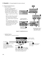
Fault Symbols
“Active Fault” and “Rate Limit” symbols provide a link to the cause of a boiler
fault or firing rate limit. The first boiler status screen provides an overview of
boiler operation including fault status.
Information Symbol
“Information” symbol links most screens to screen content explanations. New
terminology used in status and adjustment screens are explained in plain words.
Summary of Contents for Apex APX399
Page 65: ...65 VIII Electrical continued Figure 43 Ladder Diagram ...
Page 66: ...66 VIII Electrical continued ...
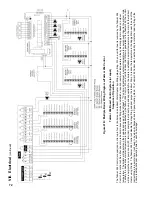
Page 67: ...67 Figure 44 Wiring Connections Diagram VIII Electrical continued ...
Page 110: ...110 1P 3 1P 2 1P 1 XIII Repair Parts continued 1C 1D 1E ...
Page 116: ...116 XIII Repair Parts continued ...
Page 118: ...118 XIII Repair Parts continued ...
Page 129: ...129 SERVICE RECORD DATE SERVICE PERFORMED ...
Page 130: ...130 SERVICE RECORD DATE SERVICE PERFORMED ...

