22
VIII Gas Piping
Gas piping to the boiler must be sized to deliver adequate gas for the boiler to fire at the nameplate input at an
inlet pressure between the minimum and maximum values shown on the rating plate. For more information on
gas line sizing, consult the utility or the
National Fuel Gas Code
.
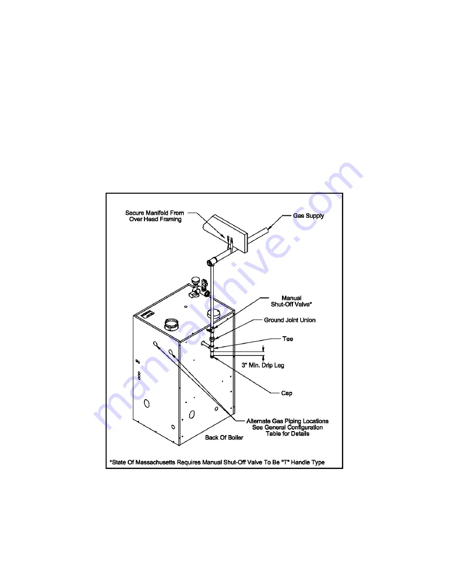
Figure 7.1 shows typical gas piping connection to the CHG boiler. A sediment trap must be installed upstream
of all gas controls. Install the factory provided manual shut-off valve outside the jacket with a ground joint
union as shown.
The boiler and its gas connection must be leak tested before placing the boiler in operation. When doing this,
the boiler and its individual shut-off must be disconnected from the rest of the system during any pressure
testing of that system at pressures in excess of 1/2 psi. When pressure testing the gas system at pressures of
1/2 psi or less, isolate the boiler from the gas supply system by closing its individual manual shut-off valve.
Figure .1: Gas Connection To Boiler
Summary of Contents for CHG CHG150
Page 25: ...25 Figure 8 3 Piping Method 1 Heat Indirect Water Heater Figure 8 2 Piping Method 1 Heat Only ...
Page 29: ...29 Figure 8 8 Piping Method 2 Heat Only Figure 8 9 Piping Method 2 Heat Indirect Water Heater ...
Page 36: ...36 Figure 9 1 Wiring Connections Diagram ...
Page 37: ...37 Figure 9 2 Ladder Diagram ...
Page 38: ...38 Figure 9 3 Wiring of Isolation Relay for Control of Two Heating Circulators ...
Page 40: ...40 CHG Series Lighting and Operating Instructions ...
Page 46: ...46 Figure 11 2 Basic Menu Tree ...
Page 54: ...54 SERVICE RECORD DATE SERVICE PERFORMED ...
Page 58: ...58 ...
Page 59: ...59 ...
Page 60: ...60 ...
Page 61: ...61 ...
Page 63: ...63 ...
Page 65: ...65 ...
Page 66: ...66 ...
Page 67: ...67 ...
Page 69: ...69 SERVICE RECORD DATE SERVICE PERFORMED ...
Page 70: ...70 SERVICE RECORD DATE SERVICE PERFORMED ...
Page 71: ...71 SERVICE RECORD DATE SERVICE PERFORMED ...
Page 72: ...9EARS IN 3ERVICE 3ERVICE HARGE AS OF 2ETAIL 0RICE O HARGE ...


