3
VIII Gas Piping
Gas piping to the boiler must be sized to deliver adequate gas for the boiler to fire at the nameplate input at an inlet
pressure between the minimum and maximum values shown on the rating plate. For more information on gas line
sizing, consult the utility or the National Fuel Gas Code.
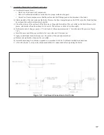
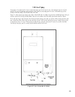
Figure 8.1 shows typical gas piping connection to the FCM boiler. A sediment trap must be installed upstream of all gas
controls. Install the factory provided manual shut-off valve outside the jacket with a ground joint union as shown.
The boiler and its gas connection must be leak tested before placing the boiler in operation. When doing this, the boiler
and its individual shut-off must be disconnected from the rest of the system during any pressure testing of that system
at pressures in excess of ½ psi. When pressure testing the gas system at pressures of ½ psi or less, isolate the boiler
from the gas supply system by closing its individual manual shut-off valve.
Figure 8.1: gas Connection To boiler
Summary of Contents for FREEDOM
Page 8: ...8 Figure 1 Wall Mounting Hole locations ...
Page 9: ...9 Figure 5 2 Boiler Mounting Hardware ...
Page 11: ...11 Figure 6 1 Boiler Installed In A Confined Space Ventilation Air From Inside ...
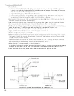
Page 42: ...42 FIGURE 7 51 CONDENSATE PIPING ARRANGEMENT ...
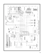
Page 55: ...55 Figure 10 1 Wiring Connections Diagram ...
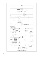
Page 56: ...56 Figure 10 2 Ladder Diagram ...
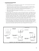
Page 57: ...57 Figure 10 3 Wiring of Isolation Relay for Control of Two Heating Circulators ...
Page 60: ...60 FCM Series Lighting and Operating Instructions ...
Page 66: ...66 FIGURE 12 2 BASIC MENU TREE ...
Page 75: ...75 ...
Page 77: ...77 ...
Page 79: ...79 ...
Page 80: ...80 ...
Page 81: ...81 ...
Page 83: ...83 150 151 152 153 154 155 ...
Page 84: ...84 156 157 158 159 160 161 ...
Page 85: ...85 162 ...

