30
c. Mount the vacuum relief valve into the tee and
fasten with a screw and nut in collar tabs. To
ensure proper operation, the gate must be level
across the pivot point and plumb. Refer to
vacuum relief valve manufacturer's instructions.
5. Install remainder of air intake, securing each joint
with at least three (3) sheet metal screws evenly
spaced.
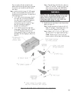
6. Install air intake terminal. See Figure 19.
E
C
I
T
O
N
s
e
h
c
n
i
2
1
t
s
a
e
l
t
a
e
b
t
s
u
m
l
a
n
i
m
r
e
t
e
k
a
t
n
I
.
n
o
i
t
a
l
u
m
u
c
c
a
w
o
n
s
s
u
l
p
e
d
a
r
g
e
v
o
b
a
7. Seal all external joints with weatherproof caulk.
G
N
I
N
R
A
W
m
u
e
l
o
r
t
e
p
e
r
e
h
w
e
k
a
t
n
i
r
i
a
e
t
a
c
o
l
t
o
n
o
D
e
l
i
t
a
l
o
v
,
s
t
n
e
g
r
e
t
e
d
,
s
'
C
F
C
,
s
e
t
a
l
l
i
t
s
i
d
.
t
n
e
s
e
r
p
e
r
a
s
l
a
c
i
m
e
h
c
r
e
h
t
o
y
n
a
r
o
s
r
o
p
a
v
l
l
i
w
e
r
u
l
i
a
f
d
n
a
n
o
i
s
o
r
r
o
c
r
e
l
i
o
b
e
r
e
v
e
S
.
t
l
u
s
e
r
Summary of Contents for MPO Series
Page 6: ...6 Figure 1 MPO 84 Thru MPO 231 Water Boiler ...
Page 22: ...22 Figure 13A Water Boiler Piping for Circulator Zoned Heating System Supply Side Circulator ...
Page 38: ...38 Figure 27 L1 L2 and V1 Head Electrode Positioning and Gun Setting Beckett AFG ...
Page 49: ...49 SERVICE RECORD DATE SERVICE PERFORMED ...
Page 50: ...50 Bare Boiler Assembly ...
Page 52: ...52 Bare Boiler Assembly ...
Page 54: ...54 Jacket Assembly ...
Page 56: ...56 MPO84 Thru MPO231 Water Boilers Trim and Controls ...
Page 58: ...58 Beckett AFG Burner ...
Page 61: ...61 Figure A2 LWCO Location ...


