1
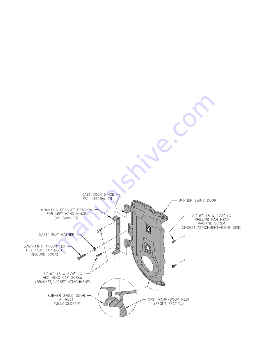
Figure 5A: Partial Front View - Burner Swing Door Mounted to Boiler - Fully Closed and Secured
1. To open/remove Burner Swing Door (mounted on
Cast Iron Section/Burner Swing Door/Smoke Box
Assembly) and door mounting bracket for front
jacket panel installation:
a. Loosen but not remove door left side latching
hardware (3/8”-16 x 1-3/4” tap bolt).
b. Loosen and remove door right side latching
hardware (3/8”-16 x 1-3/4” tap bolt and 5/16”
washer) and set aside.
c. Remove door left side latching hardware (3/8”-
16 x 1-3/4” tap bolt and 5/16” washer) and set
aside.
d. Lift the door off mounting bracket and set aside.
e. Remove two 5/16”-18 – ¾” hex head cap screws
securing door mounting bracket to front section
and set aside.
f. Remove door mounting bracket and set aside.
g. Note/mark cap screw bosses on front section
left side; locate/mark similar two bosses directly
opposite on front section right side. These four
front section bosses are front jacket panel and
door mounting bracket attachment points.
See also Figure 7 “Purpose of Tappings & Bosses”.
2. Open Jacket Carton and locate jacket front panel
(has factory attached 1” fiberglass insulation). See
also “Repair Parts” Section, “Jacket Assembly”
illustration for part identification.
3. Open Part Carton, locate Hardware Bag, remove
two 5/16”-18 x ½” Phillips pan head machine
screws.
4. Place front jacket panel over front section
attachment bosses and align jacket holes with front
section boss holes.
5. Firstly, install two 5/16”-18 x ½” Phillips pan head
machine screws hand tight to secure front jacket
panel right side to casting
6. Secondly, insert 5/16”-18 – ¾” hex head cap
screw thru door mounting bracket upper hole
and upper hole on left side of front jacket panel
simultaneously, and, fasten the bracket and panel to
casting hand tight.
7. Thirdly, insert 5/16”-18 – ¾” hex head cap
screw thru door mounting bracket lower hole
and lower hole on left side of front jacket panel
simultaneously, and, fasten the bracket and panel to
casting hand tight.
8. Finally, tighten both sets of hardware to secure the
bracket and front jacket panel.
9. Inspect fiberglass rope located on the swing door.
The rope must be evenly distributed around the
perimeter of the door groove and cannot bunch or
overhang. Repair or replace, if the rope is damaged,
or, there is a gap between the rope ends.
10. Inspect burner swing door insulation for damage and
proper type.
By design, for all models, cast bars on front section
between the combustion chamber, and, between the
left and right side 2nd and 3rd pass flueways should
make an impression in door insulation to seal the
chambers.
Summary of Contents for MST288
Page 11: ...11 Figure 4 Boiler Removal from Skid ...
Page 19: ...19 Figure 9 Float Type LWCO and Pressure Limit Installation ...
Page 25: ...25 Figure 12 Recommended Boiler Piping for Gravity Return Steam Boiler ...
Page 34: ...34 Figure 18 Wiring Diagram Steam Hydrolevel CG450 Probe LWCO ...
Page 35: ...35 Figure 18A Wiring Diagram Riello 40 Series Burner Steam Hydrolevel CG450 Probe LWCO ...
Page 36: ...36 Figure 19 Wiring Diagram Steam McDonnell Miller PS 801 Probe LWCO ...
Page 37: ...37 Figure 19A Wiring Diagram Riello 40 Series Burner Steam McDonnell Miller PS 801 Probe LWCO ...
Page 38: ...38 Figure 20 Wiring Diagram Steam McDonnell Miller 67 Float LWCO ...
Page 39: ...39 Figure 20A Wiring Diagram Riello 40 Series Burner Steam McDonnell Miller 67 Float LWCO ...
Page 45: ...45 Figure 24 L1 and V1 Head Electrode Positioning and Gun Setting Beckett AFG ...
Page 58: ...58 Bare Boiler Assembly ...
Page 60: ...60 Jacket Assembly ...
Page 62: ...62 MST288 Thru MST629 Steam Boilers Trim and Controls ...
Page 64: ...64 Beckett AFG Burner ...


