background image

5

Product Overview

Introduction

Thank you for choosing Burntech® Fireplace Solutions.

Rest  assured  our  products  have  been  tested  for  safety  and 

durability for many years when properly installed by following 

this manual completely.

Product Overview

Burntech® Fireplaces are designed as factory-built blocks to 

be  assembled  on-site. These  fireplaces  may  be  installed  on 

either combustible or non-combustible floors. In order to func

-

tion, the system requires a 10” B-vent chimney.

The main components of your 

Burntech®

 Fireplace are:

Burntech® Firebox and Smoke Dome

Gas burner, logs and control system 

(sold seperately)

B-vent

 Chimney Pipe(Sold Seperately)

The main categories of the installation of your 

Burntech®


Fireplace are:

C

learance to combustibles

Familiarity with all the components for the installation

Foundation strength of your 

Burntech®  fireplace

Chimney system measurements

Set up and use of the gas burner system.

Choice of materials and craftsmanship in fireplace and hearth 

finishing.

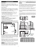
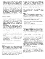
Figure 4 - Typical Installations

Internal

Wall

Installation

Corner 

Installation

Flush

Installation

Full 

Projection 

Installation

Note that each of these topics will be covered in detail and that 

the installer is expected to understand each phase completely 

before going on to subsequent instructions. 

Attention

: Be advised that all the illustrations in this manual 

are for general reference only. Do not scale drawings. Actual 

design elements will vary from case to case. Pay attention to 

specified minimum clearances to combustibles.

WARNING!

 Under no circumstances should you allow children 

to remain unattended while a fire is burning in the  fireplace! Be 

sure to keep all objects – furniture, drapes, rugs, etc. at least 

48” (48 inches) away from the opening of the fireplace!

Attention

: You may need a residential building permit to install 

a Burntech® Fireplace. Consult local jurisdictions before you 

get started

!

 The  Burntech®  gas  fireplace  is  not  designed  to  serve  as  a 

primary heat source, rather, the fireplace was expressly created 

as a supplemental source of heat. This unit is designed for use 

with the provided gas burner and approved logs only. 

Testing and listing for the Burntech® gas fireplace has been 

undertaken by PFS Test Laboratories, Inc. to ANSI Z21.50. 

Under no circumstances should the Burntech® gas fireplace be 

considered for other than in-residence buildings of conventional 

construction. 

These components make up the Burntech® gas fireplace and 

in the following pages, you will learn how they work together 

to create an exceptional unit that will give years of service and 

pleasure! 

40 5/8

"

4 3/8"

7 3/8"

A/2

11"

28

"

21"

23"

C
B

4 1/4"

A

32 7/8

"

63-1/2”

D

ø

4” OUTSIDE

 AIR


ACCESS - CAN 

BE INST

ALLED 

ON

 T

HE LEFT


SIDE ALS

O

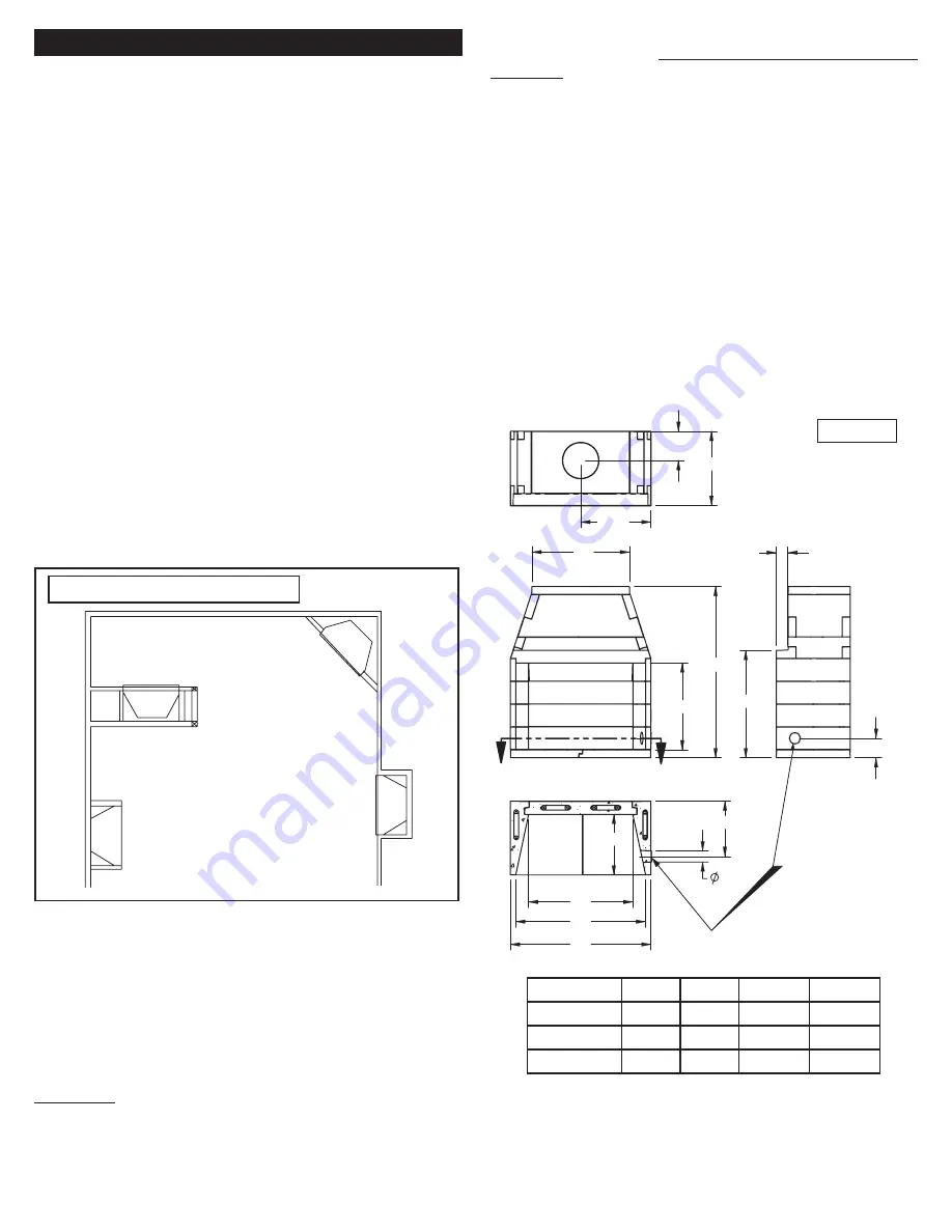
Figure 5

Overall Dimensions Burntech® Fireplaces

Model

A

B

C

D

GBVS39

43”

39”

30-1/4”

27-3/4”

GBVS44

48”

44”

35-1/4”

32-3/4”

GBVS49

53”

49”

40-1/4”

37-3/4”

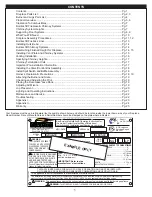
Summary of Contents for GBVS 39

Page 1: ...50 standard Solid fuels shall not be burned in this fireplace This appliance must be vented vertically through the roof This appliance is not for installation in manufactured or mobile homes The installation including provisions for combustion ventilation air and required minimum permanent vent opening must conform with the National Fuel Gas Code ANSI Z223 1 NFPA 54 and applicable local building c...

Page 2: ...THIS PAGE INTENTIONALLY LEFT BLANK ...

Page 3: ...TYPE DO NOT REMOVE THIS LABEL See Burntech Installation Operating Instructions for this model Contact local building officials about restrictions and installation specifications in your area THIS FIREPLACE IS DESIGNED FOR USE ONLY WITH THE ANSI Z21 50 DECORATIVE GAS LOGS AND BURNER TESTED AND APPROVED FOR THIS FIREPLACE Consult instructions included with this firebox for further information WARNIN...

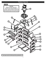
Page 4: ...mponents Warning Failure to position the parts in accordance with these diagrams or failure to use only parts specifically approved with this appliance may result in property damage or personal injury Figure 1 1 2 4 5 7 8 9 10 16 15 14 12 6 3 3A 7 8 11 17 10 18 19 ...

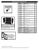
Page 5: ... DESCRIPTION QTY 1 TFS39 1 TFS44 1 TFS49 1 HEARTH Left or Right 2 2 TFS39 2 TFS44 2 TFS49 2 REAR WALL 3 3 TFS39 3 TFS44 3 TFS49 3 SIDE WALL 7 3A TFS39 3A TFS44 3A TFS49 3A SIDE WALL with 4 opening for Air Kit 1 4 TFS39 4 TFS44 4 TFS49 4 SMOKE SHELF Downdraft Diverter 1 5 TFS39 5 TFS44 5 TFS49 5 DOME REAR LOWER 1 6 TFS39 6 TFS44 6 TFS49 6 LINTEL 1 7 TFS39 7 TFS44 7 TFS49 7 DOME SIDE LOWER 2 8 TFS39...

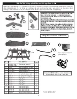
Page 6: ...ment parts and accessories as listed in these parts lists Before beginning installation be sure the burner system is complete by comparing its contents with this Parts List Parts may differ depending upon the size of the set purchased Be sure you know the model number and size of your set when ordering replacement or optional parts and accessories Burner Log Kit and remote are sold seperately WARN...

Page 7: ... illustrations in this manual are for general reference only Do not scale drawings Actual design elements will vary from case to case Pay attention to specified minimum clearances to combustibles WARNING Under no circumstances should you allow children to remain unattended while a fire is burning in the fireplace Be sure to keep all objects furniture drapes rugs etc at least 48 48 inches away from...

Page 8: ... accessories Use of other controls parts and accessories which are not designed for use with Burntech gas fireplaces is prohibited and will void all warranties certifications listings and building code approvals and may cause property damage personal injury or loss of life The burner included with this gas fireplace is non convertible and only meant to be used with the gas listed on the rating pla...

Page 9: ...ading these procedures will save you time and at the most it will prevent any malfunction that could result in property damage or serious injury Do not start the installation until you have checked out all the local regional state and national rulings laws and codes as they apply to fireplaces and fireplace installations Every community is different so do not assume that because you know the requi...

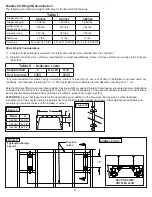
Page 10: ...the addition of floor joists to align with the anchor brackets allows the brackets to be directly connected to the floor joists Note that additional floor joists may be required to support the weight of the firebox and chimney Where the floor joists run parallel to the front of the firebox anchorage can be accomplished in like manner as shown in Figure 6 using blocking between the floor joist For ...

Page 11: ... at time of installation and used under dry conditions the deflection resulting from L 0 5D is permitted to be substituted for the deflection resulting from L D Note that Burntech cannot accept responsibility for structural floor support details All drawings are presented as mere illustrations to indicate the presence of the underlying floor system It is the responsibility of the general contracto...

Page 12: ... washers GBVS 44 49 Eight 8 pieces 3 8 rebar x 36 long included with unit Eight 8 ea All thread x 12 long with nuts and washers ALL UNITS Three 3 90 lb bags of ready mix concrete with 1 4 or smaller aggregate SURFACE CRACKS The Burntech fireplaces are manufactured using high quality materials During the drying process surface cracking may occur These small cracks under 1 16 will not affect the fir...

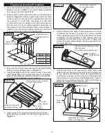
Page 13: ...flatness level if necessary Figure 13 1 2 away from edges 1 2 mortar bead typical Hearth section shown prepared for Right Side position Apply mortar bead to all mating surfaces Apply mortar to the remaining Hearth except this time apply beading on surface to be facing floor as shown in Figure 14 1 2 3 4 5 Figure 14 Hearth shown prepared for Left Side position Before installing side walls confirm p...

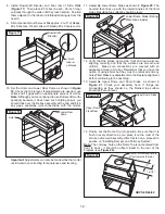
Page 14: ...eveled face lines up with the inward angles of the lintel sides Resulting top surfaces should be level Figure 20 Lower Dome Sides Rating Plate faces inside Verify that the smoke dome side front and rear walls are aligning correctly and that the surfaces are smooth and uniform Make sure connections are covered with an adequate amount of mortar Remember that you have the option of using shims but th...

Page 15: ...25 Fireplace Finishes Combustible Trim Clearances Mantel and Mantel Shelf Clearances As with any radiant heat fireplaces all Burntech Fireplaces must comply with building code safety clearances per units that have openings of 6 sq ft six square feet or greater You must keep combustibles such as trim 8 away from the firebox opening for mantel clearances see Figure 26 Combustible material Figure 26 ...

Page 16: ... in an accident or malfunction If instructions are not followed the warranty on the product will become null and void 3 1 2 3 4 5 Note that the most important aspect of the installation is the maintenance of minimum required clearances to combustible materials Those specific installation requirements must be followed with great precision as you are dealing with the potential of fire hazard if the ...

Page 17: ... 1 One elbow begins the installation procedure and the second elbow is used to finish off each section In all likelihood a 30 degreeoffsetelbowwillprobablybethefirsthardwareusedoff the top of the anchor plate damper Note Under no circumstances should you use an offset elbow in place of a return elbow They have distinct purposes in the configuration of the offset installation and they cannot be int...

Page 18: ...clination Multiple offsets are permitted if they do not exceed a 45 inclination The total lengths of the two offsets are not required to meet the 75 allowable rule Figure 2 Example 3 Shows a single offset at 45 of inclination and therefore the lateral length at 10 ft of offset does not have to meet the 75 rule In each case the offsets must be supported and firestops must be positioned wherever the...

Page 19: ...are scheduled to install the round top termination unit or any of the flashings or flues that will be exposed to outside weather conditions Venting terminals shall not be recessed into walls or siding This appliance when installed must be electrically grounded in accordance with local codes and in the absence of local codes with the National Electrical Code ANSI NFPA 70 or the Canadian Electrical ...

Page 20: ...tch sensor pointed toward the room out of the fireplace Use six 6 drywalls screws to fasten it in place on the front most part of the firebox ceiling as shown through the six 6 pre drilled holes Attach the trim plates to the left and right side of the baffle with the sheet metal screws so that the edges are flush with the firebrick Important This baffle assembly and only this one supplied with the...

Page 21: ... SOAPY WATER SOLUTION IF A LEAK IS DETECTED TIGHTEN CONNECTIONS AND TEST AGAIN NEVER USE AN OPEN FLAME TO CHECK FOR GAS LEAKS Insert a one way screw into the hole in the front of each bracket and tighten with a long min 12 screw driver until contactismadewiththegratelegandthegrateispermanently locked in place see Figure 23 IMPORTANT Once installed the burner cannot be removed Fill in the holes you...

Page 22: ...nd the heat chambers facing the back of the fireplace Figure 35 Place the front log on the grate in front of the top burner pipe with the flat down and the heat chambers toward the burner pipe and the log as far forward as possible while keeping the back parallel with the burner pipe Figure 36 Place top logs across the front and back logs in the order and positions shown in Figure 40 1 2 3 WARNING...

Page 23: ... the four 4 screws above and below the control panel face then pull the control panel out far enough to expose the test ports on the valve Figure 41 Unscrew the port marked IN part way and test CAUTION Do not kink the flex connectors coming from the valve while accessing it Figure 42 Lighting the Pilot Note Pilot flame should encircle top of electrodes See instructions cover for example of proper ...

Page 24: ...lts a Check with a millivolt meter Should be 250 millivolts or more b Pilot flame making a blowing sound b Pilot needs adjusting see Checking and Adjusting the Pilot on page 22 c Generator wire leads attached to the wrong terminals on the valve c Connect leads per wiring diagram previous page d Defective thermo magnetic safety in valve d Replace valve 2 Pilot Burning No Gas to Burner a Safety valv...

Page 25: ...oncrete slab The concrete strength and durability shall comply with Sections 1903 1904 and 1905 of the International Building Code IBC TABLE R402 2 MINIMUM SPECIFIED COMPRESSIVE STRENGTH OF CONCRETE MINIMUM SPECIFIED COMPRESSIVE STRENGTH a f c Weathering Potential b TYPE OR LOCATION OF CONCRETE CONSTRUCTION Negligible Moderate Severe Basement walls foundations and other concrete not exposed to the...

Page 26: ...ely b Lines defining areas are approximate only Local conditions may be more or less severe than indicated by region classification A severe classification is where weather conditions result in significant snowfall combined with extended periods during which there is little or no natural thawing causing deicing salts to be used extensively ...

Page 27: ...nded at Burntech Fireplace Solutions s option Nothing in this warranty makes Burntech Fireplace Solutions or any affiliate thereof liable in any respect for any injury or damage to the building or structure in which the fireplace has been installed or to the persons or property therein arising out of the use misuse or installation of properly manufactured Burntech Fireplace Solutions products The ...

Reviews: