background image

 
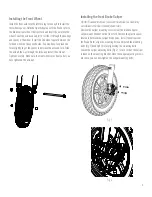
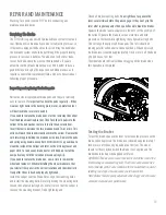
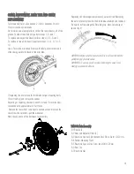
Adjusting the Brake Caliper 

After you have tightened the brake mounting bolts, squeeze the 
brake lever a couple times to set the position of the caliper. 
Squeeze the brake lever one more time and hold pressure on the 
lever while tightening the caliper adjusting bolts (Fig 2). This will 
align the caliper and brake pads. The rotor should be running 
parallel and central to the caliper body. When depressed the brake 
lever should be approximately 1 inch or more off the hand grip and 
have a firm feel. The front wheel should roll freely without dragging 
on the brake when this operation is complete 


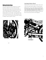
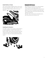
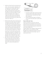
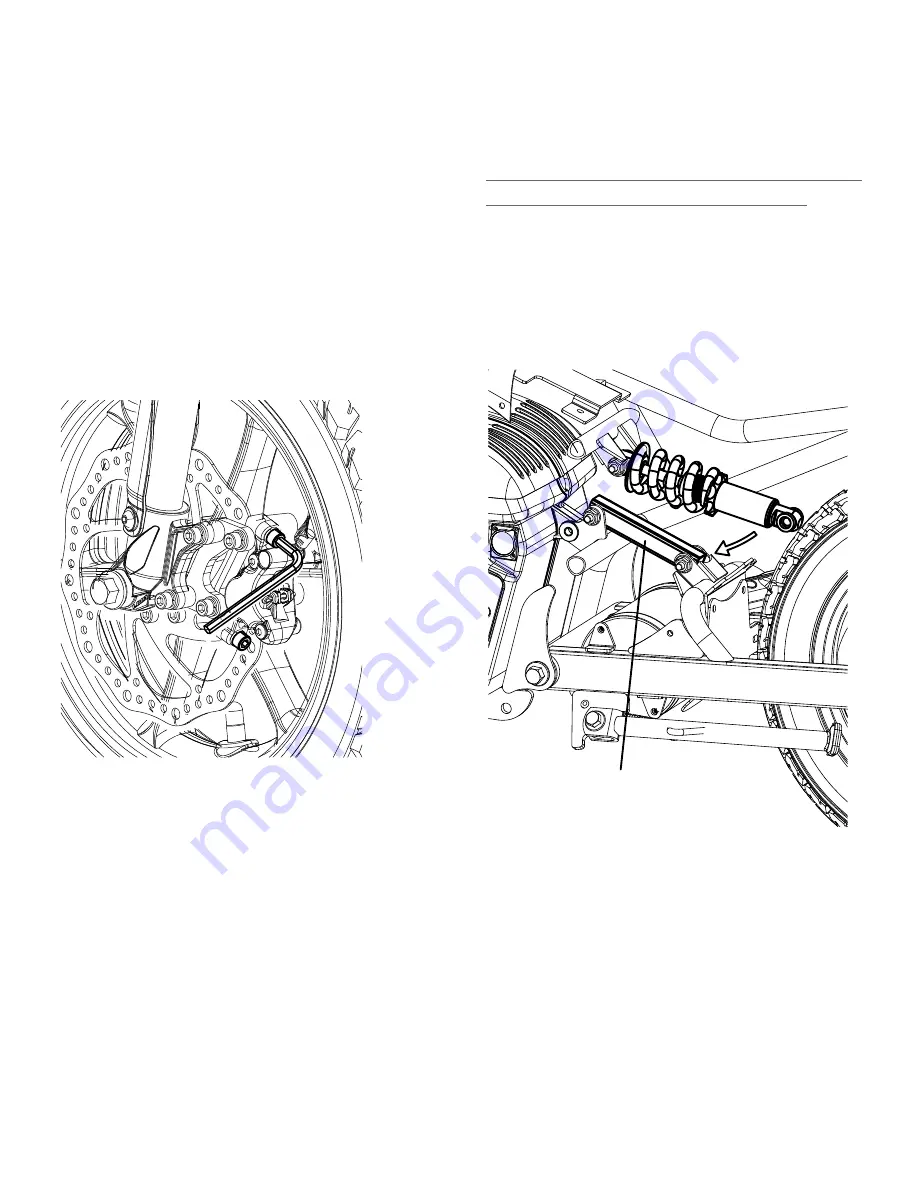
Installing The Rear Shock


The Rear shock is mounted to the top shock mount under the seat. 
There is a short tube that holds the bike in a lowered position for 
shipping purposes. The top bolt and the tube will be discarded but 

You will need the bottom bolt from the Shipping tube to 
secure the bottom of the shock to the rear fork. 

With the 

tube removed swing the shock down into place and install the bolt 
that was removed from the bottom of the shipping tube.   


Fig 2 


 remove

Summary of Contents for TT1600R

Page 1: ...OWNERS MANUAL TT1600R Mini Bike Assembly Video Features and Operation ...

Page 2: ...icles are 90 percent assembled and packed at the factory there should not be any problems even if the box has a few scars or dents Allow up to 30 Min for assembly Check for all parts and hardware before beginning assembly Follow these instructions carefully Checking all bolts Nuts and screws for tightness during the assembly process DO NOT Squeeze the brake levers until the brakes have been fully ...

Page 3: ...gently push together till you feel the connectors snap into place Do this with all wire connections Brake levers and throttle DO NOT Squeeze the brake levers until the Front Brake has been fully assembled to the bike Rotate the Brake levers into a good riding position and tighten the clamp bolts using a 5mm allen wrench Rotate the throttle to a good operating position and tighten using a 3mm allen...

Page 4: ...e nut Tighten Securely Make sure the front wheel spins freely after you have tightened the axle nut Installing the Front Brake Caliper DO NOT Squeeze the brake levers until the brake has been fully assembled to the front fork and brake rotor Remove the caliper mounting screws from the brake caliper or caliper mount Bracket on the front fork Remove the plastic spacer located in between the caliper ...

Page 5: ...roximately 1 inch or more off the hand grip and have a firm feel The front wheel should roll freely without dragging on the brake when this operation is complete Installing The Rear Shock The Rear shock is mounted to the top shock mount under the seat There is a short tube that holds the bike in a lowered position for shipping purposes The top bolt and the tube will be discarded but You will need ...

Page 6: ...eze the tire and assume it is correct For the best performance and range this must be checked regularly Low tire pressure reduces range speed and all around performance Please Note There is a tire information label located on the left side of the rear fork with this information as well Installing the Footrests The footrests are made to fit on the right and left MAKE SURE YOU ATTACH THE FOOTRESTS S...

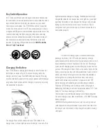
Page 7: ...hange from a red light to a green light signifying the battery is fully charged The charger will get warm during use this is normal and is no cause for concern If your charger does not get warm during use it does not mean that it is not working properly For the first 5 charge cycles we recommend that you discharge the battery to 43 45 volts and then fully recharge uninterrupted until the battery i...

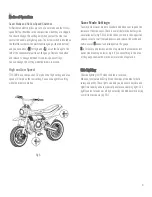
Page 8: ...an change this setting while the bike is in motion Saver Mode Settings To switch from Saver mode to Standard mode does not require the removal of the side cover There is a small hole in the battery side cover allen bolts fig 5 A and with the key switch in the on position you can insert a small tool and depress and release the switch and notice a small S appear and disappear on the gauge S is for s...

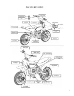
Page 9: ...9 Features and Controls ...

Page 10: ...nufacturer Like other electric products these vehicles can and are intended to move and it is therefore possible to lose control fall off and or get into dangerous situations that no amount of care instruction or expertise can eliminate If such things occur you can be seriously injured or die even when using safety equipment and other precautions RIDE AT YOUR OWN RISK AND USE COMMON SENSE It is yo...

Page 11: ...ap securely buckled A helmet may be legally required by local law or regulation in your area Long pants and gloves are recommended Always wear boots or athletic shoes never ride barefooted or in sandals and keep shoelaces tied and out of the way of the wheels motor and drive system BATTERY AND CHARGER WARNINGS 1 The charger supplied with the electric mini bike should be regularly examined for dama...

Page 12: ...th 200 lb riders and these bikes were tested to have a 44 Mile range on the low setting in saver mode 20 mph and nearly 26 miles on the high setting in saver mode 32 mph Testing was done on flat ground with wide open throttle with calm weather These bikes were tested from full charged to cutoff voltage and we don t recommend this type of usage as the normal You should familiarize yourself with the...

Page 13: ... need to replace the brake disc now is time to remove the wheel and replace it When reinstalling the wheel make sure that you reinstall the spacer in the correct locations and the wheel rolls freely after the axle has been properly tightened Install the caliper over the Brake Rotor align the mounting holes and install the mounting bolts Before tightening the mounting bolts Loosen the caliper adjus...

Page 14: ...se 14mm and 17mm wrenches loosen the axle approximately 2 full turns Remove the rear wheel remove axle nut and axle and remove the chain from the sprocket pull the wheel out Note the sequence of the hardware for assembly Replacing the chain requires removal of a master link Removing the outer retainer allows this link to be disassembled and removed Be careful not to damage the Retaining clip Note ...

Page 15: ...in to find the tight spot and confirm that you still have the free play Hold the axle adjusting bolt with one 10mm wrench and tighten the Jam Nut with the other 10mm wrench Recheck for free play and that the rear wheel rolls freely 3 Now is a good time to lube the chain with chain lube Slowly roll the wheel while spraying chain lube on the inside of the chain Roll the wheel a few more times to wor...

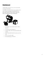
Page 16: ...y and Li ion Battery charger together Do Not attempt to replace this battery with anything other than the OEM battery 1 With the battery cover removed disconnect the hold down strap 2 Slide battery set out of mounting tray 3 Disconnect battery connection Re install new battery and reconnect 4 When reconnecting the new battery you may get a small spark 5 Tuck in wires and reassemble 6 See www burro...

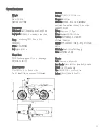
Page 17: ...e recommend 180 lb max Electrical Battery 52 Volt 23 4AH Lithium Ion Charger 58 8V 4 Amp Controller 4 Modes Hi Lo Speed Handlebar controlled Standard Saver Mode is hidden switch Locked Wheel Cut Wiring Waterproof Type Motor Brushless DC 1600W Rated Lighting LED Headlight LED Taillight LED Safety Side Lights Display MPH Odometer Voltage Charge Bar Graph Hi Low USB Ports Dual 4 5 Amp Fast Charging H...

Page 18: ...s or damage due directly or indirectly to the use of this product Burromax does not offer an extended warranty If you have purchased an extended warranty it must be honored by the store at which it was purchased For your records save your original sales receipt with this manual Fill Out the product registration page and mail it to Burromax 1 Chesterfield Mall Chesterfield MO 63017 All Warranty req...

Reviews: