background image


burster Italia s.r.l. · 

· 

· 

· Sede legale ed operativa · 

· 

· 

· Via Cesare Battisti, 16/18 · 24035 Curno (BG) · Tel. +39 035 618120 · Fax +39 035 618250 

e-mail: info@burster.it · http://www.burster.it 

C.F. e P.IVA 11048400151 · Capitale sociale Euro 49.920,00 ···· R.E.A. di Bergamo 276749 


Apparecchi di misura di precisione. Sensori e Sistemi 

per grandezze elettriche, termiche e meccaniche 

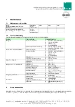
Maintenance  

7.1 

Maintenance Schedule 

Action 

Frequency 

Date 

Date 

Date 

Control of cables and connectors 

1x p.a. 


Calibration 

< 26 months 


Control of fixation (flanges, shafts) 

1x p.a. 


Have bearings exchanged by burster 

20000 hrs 
operating time 


7.2 

Trouble Shooting 

This chart is used for searching for the most frequent errors and their elimination 

Problem 

Possible Cause 

Trouble Shooting 

No signal 

No sensor excitation 


Outside of permissible range 


Connect excitation 


Cable defect 


No mains supply 


Signal output connected wrong  


Connect output correctly 


Evaluation electronics defect 

Sensor does not react to torque  

Shaft not clamped 


Clamp correctly 


No power supply 


Outside of permissible range 


Connect supply 


Cable defect 


No mains supply 


Cable defect 


Repair cable 


Connector connected wrong 


Connect correctly 

Signal has dropouts 

Axial position rotor to stator outside 
of tolerance 


Align rotor  


Cable defect 


Repair cable 

Zero point outside of tolerance 

Cable defect 


Repair cable 


Shaft mounted distorted  


Mount correctly 


Distorted shaft string 


Release from distortion 


Strong lateral forces 


Reduce lateral forces 


Distorted flanges 


Check evenness of flange-
surfaces 


Shaft overloaded 


Send to manufacturer 

Wrong torque indication 

Calibration not correct 


Re-calibrate 


Sensor defect 


Repair by manufacturer  


Torque shunt 


Eliminate shunt 

Oscillations 

Alignment of shaft not correct 


Align correctly 


Unbalance 


Balance the corresponding 
parts 


Decommission 

 
All sensors must be dismantled professionally. Do not strike sensor housings with tools. Do not apply bending moments on 
the sensor, e.g. through levers. The torque sensor must be supported to avoid falling down during the dismantling. 

Summary of Contents for 86-2113

Page 1: ...l info burster it http www burster it C F e P IVA 11048400151 Capitale sociale Euro 49 920 00 R E A di Bergamo 276749 Apparecchi di misura di precisione Sensori e Sistemi per grandezze elettriche termiche e meccaniche Operation Manual for Torque Sensors For below and similar Types 86 2113 86 2413 86 2493 86 2153 86 2453 86 2494 ...

Page 2: ...ties of the coverings and casings are Protection from detaching parts Protection from contusion and shear Prevention from reaching rotating parts Prevention from being tangled up and or getting caught by parts Coverings may Not grind Not rotate Coverings are also necessary outside of operating and motion travel areas of persons These demands can be modified if other sufficient safety devices are a...

Page 3: ...p 6 3 2 1 Sensors with Analog Output 7 3 2 2 Sensors with RS485 Interface 7 3 2 3 The Serial Communication 7 4 Mechanical Assembly 7 4 1 Typical Application 8 4 2 Housing Fixation 8 5 Electrical Connection 9 5 1 Pin Connection 9 5 2 Calibration Control 9 5 2 1 Calibration Control at Analog Output 10 5 2 2 Calibration Control at RS485 10 5 3 Cable 10 5 4 Shielding Connection 10 5 5 Running of Measu...

Page 4: ...r is fail safe and corresponds to the state of technology 1 3 1 Neglecting of Safety Notes At inappropriate use remaining dangers can emerge e g by untrained personnel The operation manual must be read and understood by each person entrusted with the assembly maintenance repair operation and disassembly of the torque sensor 1 3 2 Remaining Dangers The plant designer the supplier as well as the ope...

Page 5: ...cessary outside of operating and motion travel areas of persons These demands can be modified if other sufficient safety devices are available During operation the safety precautions must be operative By vibrations damages can occur at hand guided devices which can lead to injuries 2 Term Definitions 2 1 Terms Measuring Side Mechanical connection of the torque sensor in which the torque to be meas...

Page 6: ...ing transformer There it is rectified and stabilized With this supply the strain gauge bridge is fed For the electrical calibration control of the sensor a control signal is up modulated to the supply by the µ processor in the stator and transferred to the rotor There it is filtered and evaluated by the µPC which also activates the internal switch for the detuning of the strain gauge bridge The me...

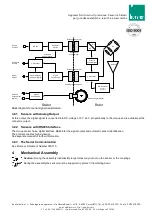
Page 7: ... Serial Data Transmission A B AC DC Filter for Control Signal Cycle and Control Signal Supply and Control Signal Rotating Transformer Block diagram for serial signal transmission 3 2 1 Sensors with Analog Output At this output the digital signal is converted into DC voltage of 0 V 5 V proportionally to the torque and is available at the connector output 3 2 2 Sensors with RS485 Interface The torqu...

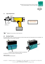
Page 8: ...meccaniche 4 1 Typical Application Caution Do not use pulse or impact wrenches 4 2 Housing Fixation The housing may not rotate This must be avoided by a flexible fixation axial and radial tolerance must be available The connection cable may not be used as a twist lock See data sheet for the exact position of the threaded holes Fixation examples Coil spring thread rod with dead stop AC C U S chraub...

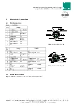
Page 9: ...oldering side 1 Excitation 12 28 VDC 2 Excitation GND 0 V 3 Signal 5 V 10 V 4 Signal GND 0 V 5 Calibration control L 2 0 V H 3 5 V 6 Option angle A TTL 7 Option angle B TTL 8 NC 12 pin Analog Digital View socket on soldering side A NC NC B Option angle B TTL Option angle B TTL C Signal 5 V 10 V NC D Signal GND 0 V NC E Excitation GND 0 V Excitation GND 0 V F Excitation 12 28 VDC Excitation 12 28 V...

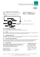
Page 10: ... our sensors and meet the metrological requirements 5 4 Shielding Connection In combination with the sensor and the external electronics the shield forms a Faraday Cage By this electro magnetic disturbances do not have any influence on the measurement signal 5 5 Running of Measuring Cables Do not run measuring cables together with control or heavy current cables Always assure that a large distance...

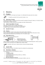
Page 11: ...e 6 4 Dynamic Torques 6 4 1 General The static calibration procedure of torque sensors is also valid for dynamic applications Note The frequency of torques must be smaller than the natural frequency of the mechanical measurement setup The band width of alternating torque must be limited to 70 of the nominal torque 6 4 2 Natural Resonances Estimate of the mechanical natural frequencies 2 1 0 1 1 2 ...

Page 12: ...ectronics defect Sensor does not react to torque Shaft not clamped Clamp correctly No power supply Outside of permissible range Connect supply Cable defect No mains supply Cable defect Repair cable Connector connected wrong Connect correctly Signal has dropouts Axial position rotor to stator outside of tolerance Align rotor Cable defect Repair cable Zero point outside of tolerance Cable defect Rep...

Page 13: ...es with oil before storing rust 10 Disposal The torque sensors must be disposed according to the valid provisions of law For this see our General Terms and Conditions www burster it 11 Calibration At the time of delivery torque sensors have been adjusted and tested with traceable calibrated measuring equipment at factory side Optionally a calibration of the sensors can be carried out 11 1 Propriet...

Reviews: