background image


Information on protection of the environment 


Product manual 2CKA001473B8289 

8  


Information on protection of the environment 

3.1 

Environment 


Consider the protection of the environment! 

Used electric and electronic devices must not be disposed of with domestic 
waste. 
–  The device contains valuable raw materials which can be recycled. 

Therefore, dispose of the device at the appropriate collecting depot. 


All packaging materials and devices bear the markings and test seals for proper disposal. 
Always dispose of the packaging material and electric devices and their components via the 
authorized collecting depots and disposal companies. 

The products meet the legal requirements, in particular the laws governing electronic and 
electrical devices and the REACH ordinance. 

(EU Directive 2012/19/EU WEEE and 2011/65/EU RoHS) 

(EU REACH ordinance and law for the implementation of the ordinance (EC) No.1907/2006). 


Summary of Contents for 1094 U

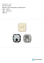
Page 1: ...2CKA001473B8289 05 07 2018 Product manual Electronic room temperature controller insert 1094 1097 U 1094 1097 UTA 1095 UF ...

Page 2: ...on commissioning and maintenance 6 2 5 Safety instructions 7 3 Information on protection of the environment 8 3 1 Environment 8 4 Setup and function 9 4 1 Functions 9 4 2 Features of function and equipment 9 4 3 Possible combinations 10 5 Technical data 11 6 Connection installation mounting 12 6 1 Requirements for the electrician 12 6 2 Mounting dismantling 13 6 3 Electrical connection 15 7 Commis...

Page 3: ...e to property and ensure both reliable operation and a long service life for the device Please keep this manual in a safe place If you pass the device on also pass on this manual along with it Busch Jaeger accepts no liability for any failure to observe the instructions in this manual If you require additional information or have questions about the device please contact Busch Jaeger or visit our ...

Page 4: ... the signal word Danger indicates an imminently threatening danger which leads to death or serious irreversible injuries Warning Serious damage to health The respective warning symbol in connection with the signal word Warning indicates a threatening danger which can lead to death or serious irreversible injuries Caution Damage to health The respective warning symbol in connection with the signal ...

Page 5: ...le surface mounted housings Use with the connecting options available on the device The intended use also includes adherence to all specifications in this manual 2 3 Improper use Each use not listed in Chapter 2 2 Intended use on page 5 is deemed improper use and can lead to personal injury and damage to property Busch Jaeger is not liable for damages caused by use deemed contrary to the intended ...

Page 6: ...The electrical installer must have read and understood the manual and follow the instructions provided The electrical installer must adhere to the valid national regulations in his her country governing the installation functional test repair and maintenance of electrical products The electrical installer must be familiar with and correctly apply the five safety rules DIN VDE 0105 EN 50110 1 Disco...

Page 7: ... qualified electricians Disconnect the mains power supply before installation disassembly Never use the device with damaged connecting cables Do not open covers firmly bolted to the housing of the device Use the device only in a technically faultless state Do not make changes to or perform repairs on the device on its components or its accessories Keep the device away from water and wet surroundin...

Page 8: ...e of the device at the appropriate collecting depot All packaging materials and devices bear the markings and test seals for proper disposal Always dispose of the packaging material and electric devices and their components via the authorized collecting depots and disposal companies The products meet the legal requirements in particular the laws governing electronic and electrical devices and the ...

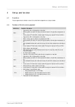
Page 9: ...o valves of closed when de energized design are required for the controller UF With normally closed contact With remote sensor external temperature sensor for mounting in the floor and thermal feedback For electric floor heating Opening of the relay contact when the set temperature is reached 1096 Opens when the set temperature is reached With separate connection for time controlled reduction of n...

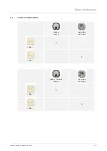
Page 10: ...Setup and function Product manual 2CKA001473B8289 10 4 3 Possible combinations 1094 U 1097 U 1094 UTA 1097 UTA 1794 X 1794 X 1095 U 1095 UF 1096 U 1095 UTA 1096 UTA 1795 X 1795 X ...

Page 11: ...1094 1095 U 1095 UTA 1096 1097 1 5 mm 2 5 mm 1095 UF 2 x 2 5 mm 1 x 4 mm Temperature adjustment range 1094 1095 U 1095 UTA 1096 1097 1 6 5 30 C 1095 UF 1 6 10 50 C Temperature reduction 4 K Switching temperature difference 0 5 K Protection type IP 20 EN 60529 Remote sensor 1095 UF NTC 10 kΩ 25 C Sensor line length 1095 UF 4 m Ambient temperature range 0 30 C Mode of operation DIN EN 60730 1 1B Deg...

Page 12: ...our life and that of the user of the electrical system Incorrect installation can cause serious damage to property e g due to fire The minimum necessary expert knowledge and requirements for the installation are as follows Apply the five safety rules DIN VDE 0105 EN 50110 1 Disconnect 2 Secure against being re connected 3 Ensure there is no voltage 4 Connect to earth and short circuit 5 Cover or b...

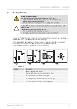
Page 13: ...ith screwdrivers or similar hard objects In Germany the flush mounted insert must only be installed in flush mounted boxes according to DIN 49073 1 Part 1 or suitable surface mounted housings Different installation standards apply in other countries These are to be taken into account when used in connection with a different support ring and flush mounted box The temperature controller is suitable ...

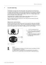
Page 14: ...1 2 1 2 4 3 4 3 3 Seat the cover plate 1 on the insert 4 Attach the adjusting knob 3 Before attaching the adjusting knob turn the two arrows toward each other basic setting Attach the adjusting knob vertically so that the position lug 4 engages in the recess of the drive plate 2 Fig 2 Attaching the adjusting knob Notice In connection with hot water heating servo valves of closed when de energized ...

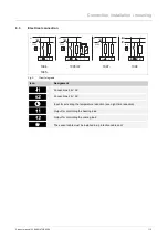
Page 15: ... 16A 230V 230V 230V 24V 1094 1095 1095 UF 1097 1096 Fig 3 Circuit diagrams Icon Assignment Connections 24 V AC Connections 24 V AC Input for activating the temperature reduction see night time reduction Output for controlling the heating load Output for controlling the cooling load The sensor cable must be installed in a protective cable duct ...

Page 16: ...t 8 minutes Offset function scale correction Reaching the selected room temperature depends on the ambient conditions such as heating system capacity at least 5 K h min room size ambient temperature insulation etc That is why the values in the scale are merely guide values To perform a setting that is as accurate as possible the adjusting knob can be offset in 4 stages by a total of 6 C as follows...

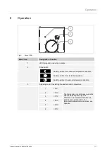
Page 17: ...itch position for selected temperature Switch position for external temperature reduction 3 Adjusting knob for selecting the desired room temperature 1 5 C The temperature is continuously variable with the adjusting knob 3 The difference in temperature between two digits is approximately 5 C For temperature adjustment and values see opposite 2 10 C 3 15 C 4 20 C 5 25 C 6 30 C 1 2 3 4 5 6 1 2 3 4 5...

Page 18: ...roduct manual 2CKA001473B8289 18 Fig 6 Cover with excerpt 1795 TA Mark Icon Designation Function 4 Icon in the display Heating switched on Temperature reduction active Calibration 1 2 3 4 5 6 1 2 3 4 5 6 4 4 CA CA ...

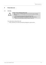
Page 19: ...ts these can enter the device through crevices Do not spray cleaning agents directly onto the device Aggressive cleaning agents can damage the surface of the device Never use caustic agents abrasive agents or solvents Clean dirty devices with a soft dry cloth If this is insufficient the cloth can be moistened slightly with a soap solution ...

Page 20: ...res of functions 9 Functions 9 I Improper use 5 Information and symbols used 4 Information on protection of the environment 8 Intended use 5 M Maintenance 19 Mounting 13 N Notes on the instruction manual 3 O Operation 6 17 P Possible combinations 10 Q Qualification of personnel 6 R Requirements for the electrician 12 S Safety 4 Safety instructions 7 Setup and function 9 T Target group 6 Technical ...

Page 21: ...tents of this document without prior notice The detailed specifications agreed upon apply for orders ABB accepts no responsibility for possible errors or incompleteness in this document We reserve all rights to this document and the topics and illustrations contained therein The document and its contents or extracts thereof must not be reproduced transmitted or reused by third parties without prio...

Reviews: