6.3
Switching the detector on
Set the circuit breaker
to
I
(see 4.
3
)
.
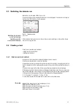
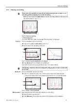
The various stages for switching the detector on are displayed. The detector is ready for
testing when the Stand-by screen appears.
Switching the detector
on for the first time
Switching on after
an extended shutdown
Fig.
10
:
Stand-by screen
(see 5.6)
If the detector has been stored or has not been used, switching on time will be longer
than if it is in regular use.
6.
4
Starting a test
There are 2 possible test methods:
6.4.1 Hard vacuum test method
Part that can be connected to pipe and placed under a vacuum.
Part that can be placed in a vacuum chamber.
This method involves removing the air from the part to be tested, connecting it to the de-
tector's analyzer cell, then spraying tracer gas on the points of the part that are likely to
leak.
The detector measures the flow of tracer gas that penetrates due to part leakage.
When spraying starts, the leak rate is not displayed instantaneously: there is a response
time which depends on the volume V being tested and the tracer gas pumping speed S
of the system at the opening of the part, according to the following relation:
T = V/S (where T = seconds, V = litres, S = l/s).
T is the time required for the leak rate to reach 63 % of the final value.
-
Hard vacuum test method
-
Sniffing test method
Procedure
Select the ’hard vacuum’ test method (see 7.4.1).
Set the test mode (see 7.4.3)
.
Set the reject set point if necessary (see 7.3.3).
Set the detector to Stand-by mode.
Prepare the part to be tested.
27
0870231897_0001_IM_en
Operation
Summary of Contents for 0659230708
Page 79: ...Note 79 0870231897_0001_IM_en...

