OPERATION
1947/2047 01/11
Operation Section 4-8
© 2011 Alamo Group Inc.
OPERA
T
ION
3.3 Tractor Ballast
Before operating tractor and loader, add sufficient counterweight so a minimum of 25% of the
total weight is on the rear axle. Total weight includes weight of: tractor, loader, rated load in
bucket, and counterweight. Rated load is lift capacity at full height at 500mm forward of
bucket pivot point (See Standard Equipment and Specifications). When determining required
counterweight bucket should be at maximum forward position (bucket pivot point at the same
height as boom pivot point on mast).
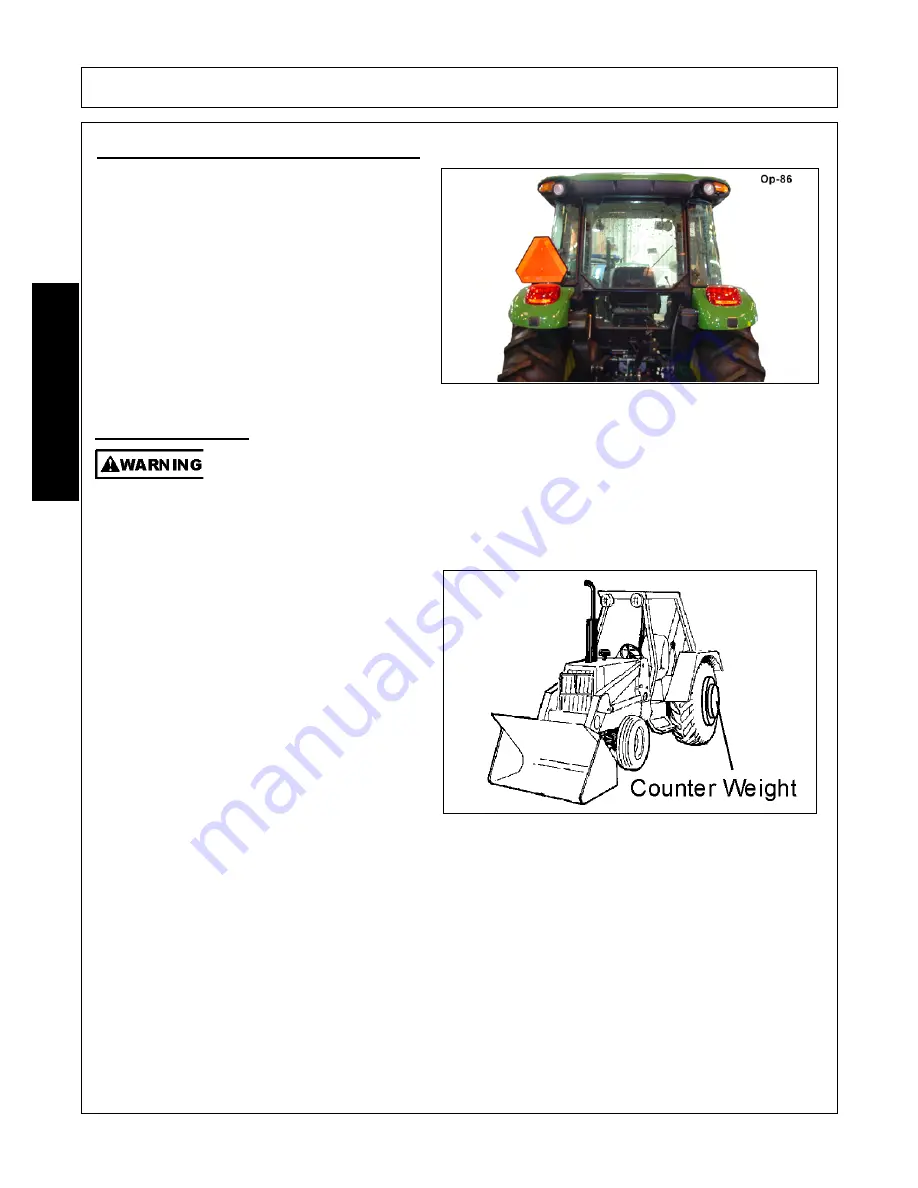
3.2 Tractor Lighting and SMV Emblem
If the tractor will be operated near or traveled on a
public roadway it must be equipped with proper
warning lighting and a Slow Moving Vehicle (SMV)
emblem which are clearly visible from the rear of
the unit. Most tractor’s have different settings for
operating and transporting lighting. Refer to the
tractor operator’s manual for using the tractor’s
light switch and operating the turn signals.
OPS-B- 0017
To ensure tractor stability when operating add
wheel ballast or rear weights to rear tractor tires.
For better stability, use tractor with wide front axle
rather than tricycle front wheels. Move wheels to
the tractor manufacturer’s widest recommended
settings to increase stability. If 3-Point hitch
counterweights are used, they should be carried
as low as possible at all times to maximize stability.
Effective counterbalance weight at rear axle of
mounted rear equipment is determined by
multiplying actual weight of equipment by 1.50.
EXAMPLE:
Equipment weighing 800 pounds,
attached to tractor, multiplied by 1.50, equals 1200
pounds of effective counterbalance weight at rear
axle.
A tractor that does not meet this criteria is
DANGEROUS and should not be operated as
upset of the unit can occur resulting in possible
serious injury and property damage.
OPS-L-
0001_A
Summary of Contents for 1947
Page 5: ...Safety Section 1 1 SAFETY SECTION...
Page 27: ...Introduction Section 2 1 INTRODUCTION SECTION...
Page 32: ......
Page 33: ...Assembly Section 3 1 ASSEMBLY AND CONNECTING THE LOADER SECTION...
Page 37: ...ASSEMBLY 1947 2047 01 11 Assembly Section 3 5 2011 Alamo Group Inc ASSEMBLY...
Page 40: ......
Page 41: ...Operation Section 4 1 OPERATION SECTION...
Page 85: ...Maintenance Section 5 1 2011 Alamo Group Inc MAINTENANCE SECTION...
Page 97: ...MAINTENANCE 1947 2047 01 11 Maintenance Section 5 13 2011 Alamo Group Inc MAINTENANCE...
Page 98: ...MAINTENANCE 1947 2047 01 11 Maintenance Section 5 14 2011 Alamo Group Inc MAINTENANCE...
Page 99: ......
Page 102: ...1947 2047 SOM 01 11 P N 50069199 Printed U S A 1947 2047 LOADER...


