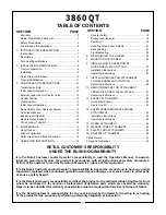
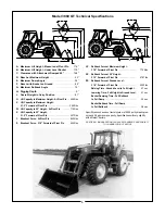
background image

SECTION

PAGE

3860 QT

TABLE OF CONTENTS

SECTION

PAGE

Warranty .....................................................................2

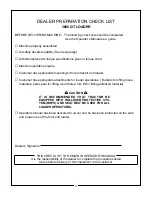
Dealer Preparation Check List....................................3

Safety Precautions .....................................................4

Federal Laws & Regulations.......................................6

1.

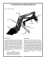
INTRODUCTION & DESCRIPTION ...........................7

Introduction.................................................................7

Description..................................................................7

Technical Specifications .............................................8

2.

INSTALLATION INSTRUCTIONS ..............................9

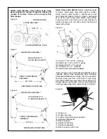
Tractor Preparation.....................................................9

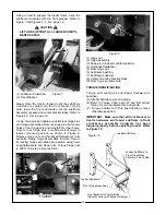
Installation ..................................................................9

Quick Draw Latch Attach ..........................................10

Torque Identification .................................................11

3.

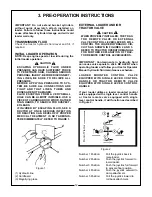
PRE-OPERATION INSTRUCTIONS........................12

Transmission Fluid ...................................................12

Initial Loader Operation ............................................12

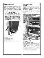
External Loader and/or Tractor Valve.......................12

Neutral Position ........................................................13

Float Position............................................................13

Initial Loader Operation ............................................13

Removing Air From Hydraulic System......................13

Hose Identification ....................................................13

Bucket Level INdicator..............................................13

Remote Hoses Support ............................................14

Third Cylinder Tube Kit.............................................14
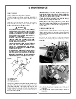
4.

MAINTENANCE .......................................................15

Daily Checks.............................................................15

Loader Lubrication....................................................15

Quick Draw Latch Attach Lubrication .......................16
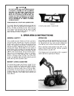
5.

OPERATING INSTRUCTIONS ................................16

RETAIL CUSTOMER’S RESPONSIBILITY

UNDER THE BUSH HOG WARRANTY

It is the Retail Customer and/or Operator’s responsibility to read the Operator’s Manual, to operate,
lubricate, maintain and store the product in accordance with all instructions and safety procedures.
Failure of the operator to read the Operator’s Manual is a misuse of this equipment.

It is the Retail Customer and/or Operator’s responsibility to inspect the product and to have any part(s)
repaired or replaced when continued operation would cause damage or excessive wear to other parts
or cause a safety hazard.

It is the Retail Customer’s responsibility to deliver the product to the authorized Bush Hog Dealer, from
whom he purchased it, for service or replacement of defective parts which are covered by warranty.
Repairs to be submitted for warranty consideration must be made within forty-five (45) days of failure.

It is the Retail Customer’s responsibility for any cost incurred by the Dealer for traveling to or hauling
of the product for the purpose of performing a warranty obligation or inspection.

1

General Safety..........................................................16

Bucket Level Indicator ..............................................16

Operation..................................................................16

Handling Large Heavy Objects.................................21

Back Grading............................................................21

Troubleshooting........................................................22

6.

DISMOUNTING THE LOADER ................................23

7.

MOUNTING THE LOADER ......................................25

8.

INSTALLATION & OPERATION OF

QUICK DRAW LATCH ATTACH ..............................27

Installation Instructions .............................................27

Operating Instructions ..............................................27

9.

INSTALLING BUCKET OR ATTACHMENT

TO QUICK DRAW LATCH ATTACH ........................29

Operating Instructions ..............................................29

10. REMOVING BUCKET OR ATTACHMENT

FROM QUICK DRAW LATCH ATTACH ..................31

Operating Instructions ..............................................31

11. BUCKET ATTACHMENT .........................................32

Quick Draw Bucket ...................................................32

Single Tine Kit ..........................................................32

12. SUPER PENETRATOR BALE PROBE

ATTACHMENT .........................................................33

Installation Instructions .............................................33

Operating Instructions ..............................................33

13. DOZER ATTACHMENT ...........................................34

14. MANURE FORK ATTACHMENT .............................34

15. PALLET FORK ATTACHMENT................................35

16. GRAPPLE ATTACHMENT .......................................36

Safety Decals..................................................................41

Torque Specifications .....................................................43

Summary of Contents for 3860 QT

Page 1: ...OPERATION l l MAINTENANCE 208 4 00 25H51137 Model 3860 QT Front End Loader Operator s Manual BUSH HOG...

Page 2: ...h are manufactured with the same precision and skill as our original equipment Our trained service personnel are well informed on methods required to service Bush Hog equipment and are ready and able...

Page 3: ...and to have any part s repaired or replaced when continued operation would cause damage or excessive wear to other parts or cause a safety hazard It is the Retail Customer s responsibility to deliver...

Page 4: ...Hog duty taxes charges for normal service or adjustment loss of crops or any other loss of income rental of substitute equipment expenses due to loss damage detention or delay in the delivery of equi...

Page 5: ...attachments for loader operations Buckets for lifting loose materials bale spear for lifting round bales fork lift for lifting palletized material Operators manual has been delivered to owner and he...

Page 6: ...he tractor at low speeds 7 Stop tractor engine place transmission in park or neutral engage parking brake lower loader arms to ground cycle all hydraulic controls to relieve pressure allow machine mov...

Page 7: ...all persons particularly small children The operator should cease operation whenever anyone comes within the operating area 5 Operate the loader from the Operator s Seat Only 6 Exercise caution when o...

Page 8: ...not limited to instructions to Keep all guards in place when the machine is in operation Permit no riders on equipment Stop engine disconnect the power source and wait for all machine movement to stop...

Page 9: ...ng the direction of forward travel with implement properly attached to tractor DESCRIPTION The model 3860 Front End Loader Figure 1 is designed for two and four wheel drive tractors It comes equipped...

Page 10: ...d of Pivot Pin 4970 lbs Y Breakout Force At Pivot Pin 8400 lbs Z Breakout Force 31 5 Forward of Pivot Pin 6050 lbs VV Rollback Force at Maximum Height 31 5 Forward of Pivot Pin 7706lbs XX Rollback For...

Page 11: ...ounting Kit Remove all loader components from shipping packag ing IMPORTANT NOTICE This loader has both standard and metric fasteners Verify that the proper fasteners are placed in the correct locatio...

Page 12: ...ttach instructions Following these instructions will add stability to loader package and will allow easier handling of loader with a hoist Figure 5 1 Top pin 1 1 8 x 6 7 8 2 places 2 Bottom pin 1 1 8...

Page 13: ...assemblies into position using hard ened flatwashers and hinge nuts Torque hinge nuts to 200 ft lb Refer to Figures 8 9 FIGURE 8 7 2 4 1 6 3 5 8 9 7 3 Figure 9 Figure 7 1 Hinge nut 2 Hinge assembly 3...

Page 14: ...3 1 Figure 1 Figure 2 Number 1 Position Pull the joystick back to raise loader Number 2 Position Push the joystick forward to lower loader Number 3 Position Push the joystick full forward to activate...

Page 15: ...he loader bucket approximately four 4 feet above the ground and cycle the bucket cylinders two or three times Lower the bucket or attachment to the ground Check the tractor hydraulic fluid level and f...

Page 16: ...RY 3 1 4 5 2 THIRD CYLINDER TUBE KIT OPTIONAL Install two steel tubes to inside of right hand loader boom Then connect the two hoses and fittings to the front of the steel tubes Refer to Figure 6 for...

Page 17: ...ine 2 Cardboard 3 Magnifying glass Service your loader at the intervals and locations as specified When you service your loader use only high quality lubricants The engine hour meter on the tractor sh...

Page 18: ...s injury or death It is recommended that tractor be equipped with Rollover Protective System ROPS and a seat belt be used per tractor manu facturer s recommendations Check for ditches stumps holes or...

Page 19: ...f material loaded in a given period of time Time is lost if two or more attempts are made to fill the bucket on each pass LIFTING THE LOAD WARNING DO NOT LIFT OR CARRY ANYONE IN THE BUCKET OR ON ANY O...

Page 20: ...HILLSIDE IS DANGEROUS EXTREME CARE IS RECOMMENDED DO THIS NOT THIS When transporting the load keep the bucket as low as possible to avoid tipping in case a wheel drops in a rut NOT THIS DO THIS DUMPIN...

Page 21: ...DING FROM A BANK Choose a forward gear that provides sufficient ground speed for loading Exercise caution when undercutting high banks Dirt slides can be dangerous Load from as low as possi ble for ma...

Page 22: ...cise cut LOADING LOW TRUCKS OR SPREADERS FROM A PILE For faster loading minimize the angle of turn and length of run between pile and spreader Backgrade occasionally with a loaded bucket to keep the w...

Page 23: ...nd the ground must not be more than 15 degrees Refer to Figure 1 Failure to follow these instructions could cause loader attachment cylinders to fail and void warranty 15 Degrees Possibility of rollin...

Page 24: ...eater Check loader specifications than boom lift capacity Check tractor system Internal boom cylinder leakage Replace any worn parts and install a seal repair kit Improper hydraulic valve Repair or re...

Page 25: ...er Position the tractor loader on a hard level surface Raise loader boom assembly Position the bucket 90 to the ground Then lower the loader boom until front edge of bucket is resting on the ground Re...

Page 26: ...sher 5 Rear hinge pin 6 Subframe bushing 7 Subframe pedestal 8 Center mounting bracket tubes Figure 6 9 Rear hinge pin outer hole Figure 6 1 4 6 5 3 2 3 9 8 7 Figure 6 Start the tractor and position t...

Page 27: ...ENGINE LOCK BRAKES RELIEVE HYDRAULIC PRES SURE AND REMOVE KEY DO NOT STAND WALK OR WORK UNDER A RAISED LOADER OR ATTACHMENT UNLESS IT IS SECURELY BLOCKED OR HELD IN POSITION ACCIDENTAL MOVE MENT OR A...

Page 28: ...6 page 24 Raise the loader boom and position the bucket 90 to the ground Lower the loader boom assembly until front edge of bucket is resting on the ground Refer to Figure 3 Figure 2 1 Remove the two...

Page 29: ...XCEPT WHEN DETACHING OR ATTACH ING A QUICK DRAW BUCKET OR ATTACH MENT TO YOUR QUICK DRAW LATCH ATTACH ALWAYS POSITION THE QUICK DRAW HANDLE IN THE HANDLE ENGAGED POSITION FIGURE 6 PAGE 28 THIS WILL PR...

Page 30: ...n center support 3 Bucket or attachment QUICK DRAW HANDLE DISENGAGED POSITION To position quick draw handle into the handle disen gaged position pull quick draw handle to the left as shown in Figure 4...

Page 31: ...draw handle located in handle disengaged position Roll quick draw latch attach forward by extending attachment cylinders just enough to allow quick draw tubes to engage quick draw attachment channel D...

Page 32: ...d checking to be sure quick draw bucket or attachment does not roll out of quick draw latch attach Refer to Figure 5 Figure 4 Figure 5 WARNING A QUICK DRAW BUCKET OR ATTACHMENT THAT IS NOT SECURELY LO...

Page 33: ...bucket or attachment level with ground and approximately 1 off of ground Refer to Figure 1 Then pull quick draw handle into the han dle disengaged position and lock into quick draw notch Refer to Figu...

Page 34: ...OR CABLE UNLESS LOADER IS EQUIPPED WITH A BUSH HOG FACTORY APPROVED ATTACHMENT WHICH WAS DESIGNED AND BUILT FOR THIS TYPE OF LIFTING ALWAYS FOLLOW LIFTING INSTRUCTIONS INCLUDED WITH THIS ATTACHMENT N...

Page 35: ...ORGED STEEL AND SHOULD NOT BE WELDED OR HEAT TREATED IMPORTANT Maximum load limit on super pene trator bale probe is 2 200 pounds INSTALLATION INSTRUCTIONS IMPORTANT Refer to pages 29 30 for instruc t...

Page 36: ...ng stands in parked position Disconnect from quick draw latch attach as shown on page 31 Figure 1 shows dozer attachment with parking stands in parked position Refer to Figure 1 Figure 1 1 Parked posi...

Page 37: ...oader with pallet fork attached fork tines must be adjusted out ward and locked behind parking angles before parking loader Refer to Figure 1 INSTALLATION INSTRUCTIONS IMPORTANT Refer to pages 29 30 f...

Page 38: ...ay bales carrying silage and cleaning up brush Refer to Figure 1 Figure 1 NOTE Optional extended length grapple tines are available on some grapple bucket configura tions Contact Factory for further i...

Page 39: ...ers to grapple pedestals using 1 1 8 x 6 1 2 pins Install grapple cylinders to swing arm using 1 1 8 x 4 1 2 pins Secure all pins using clevis pins and cotters Install 90 fittings into cylinder ports...

Page 40: ...ird cylinder tube kit Connect hoses so that grapple operates as shown below Refer to Figure 9 Lift Cylinder Circuit Pull the handle back to raise unit Push the handle forward to lower unit Push handle...

Page 41: ...Right 9 1 Quick Coupler Mount 10 1 Hex Bolt 3 8 16NC x 3 1 2 Grade 5 11 2 Flatwasher 3 8 Ref Qty Description 12 2 Hex Nut 3 8 Nylon Lock 13 1 Hex Bolt 3 8 16NC x 1 3 4 Pin On Bucket only or 1 Weld on...

Page 42: ...NTAL INSTRUCTIONS FOR FORD GENESIS SPECIAL Refer to Form BHF 1820 Packing List and Installation Instructions includ ed with your BHF 82356 Mounting Kit for detailed Operation Instructions specific for...

Page 43: ...on request provide safety decals for any of our products in the field at no charge Contact your authorized Bush Hog dealer for more information REAR VIEW OF SUBFRAME Decals 25H46070 25H46071 25H46010...

Page 44: ...TOW ANY POINT OF THE LOADER WITH A CHAIN ROPE OR CABLE 4 DO NOT APPLY TRACTOR PULL OR PUSH FORCE TO THIS CLEVIS MOUNTING POINT APPLY ONLY LOADER HYDRAULIC LIFT OR ROLLBACK CAPACITY TO THIS CLEVIS MOUN...

Page 45: ...54 480 795 1077 1288 1745 1 11 16 1 1 8 12 UNF 397 538 890 1206 1444 1957 1 7 8 1 1 4 7 UNC 500 678 1120 1518 1817 2462 1 7 8 1 1 4 12 UNF 553 749 1241 1682 2013 2728 2 1 16 1 3 8 6 UNC 655 887 1470 1...

Page 46: ...P O Box 1039 l l Selma AL 36702 1039 Telephone 334 874 2700 l l www bushhog com...

Reviews:

Related manuals for 3860 QT