


13. DOZER ATTACHMENT
CAUTION
TO HELP PREVENT BODILY INJURY,
ALWAYS PARK AND STORE DOZER
ATTACHMENT WITH PARKING STANDS IN
PARKED POSITION.
IMPORTANT: Do not park loader with dozer
attachment attached. Always detach loader with
bucket or other factory approved attachment
attached.
INSTALLATION INSTRUCTIONS
IMPORTANT: Refer to pages 29 & 30 for instruc-
tions concerning Installing Attachment to Quick
Draw Latch Attach.
IMPORTANT: Refer to page 31 for instructions
concerning Removing Attachment from Quick
Draw Latch Attach.
A straight dozer is available in 84 inch and 96 inch
widths.
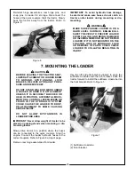
OPERATING INSTRUCTIONS FOR
DISMOUNTING DOZER FROM LOADER
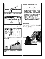
Remove parking stands from stored position.
Position parking stands in parked position.
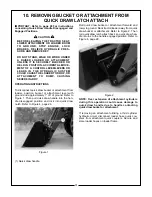
Disconnect from quick draw latch attach as shown
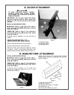
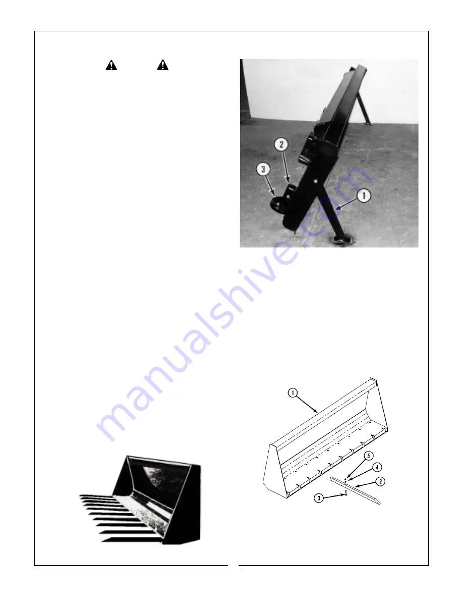
on page 31. Figure 1 shows dozer attachment with
parking stands in parked position. Refer to Figure 1.
Figure 1
(1) Parked position
(2) Storage position
(3) Adjustable skid
14. MANURE FORK ATTACHMENT
INSTALLATION INSTRUCTIONS
IMPORTANT: Refer to pages 29 & 30 for instruc-
tions concerning Installing Attachment to Quick
Draw Latch Attach.
IMPORTANT: Refer to page 31 for instructions
concerning Removing Attachment from Quick
Draw Latch Attach.
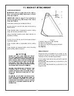
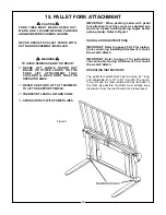
A manure fork is available in a 72" width. The
manure fork utilizes 10 each of 1-1/2" x 1" x 33"
tines. Refer to Figure 1.
Figure 1
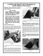
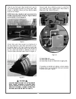
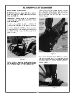
Install tines to manure fork using hardware included.
Position plow bolt head on underside of manure fork.
Refer to Figure 2.
(1) Manure fork assembly.
(2) Manure fork tine.
(3) Plow bolt 3/8"-16NC x 3" Grade 5.
(4) Flatwasher, 3/8".
(5) Hex nut 3/8"-16NC 2 way lock.
Figure 2
34


