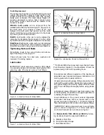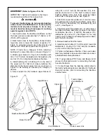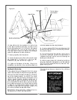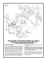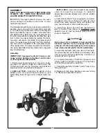
10. Align RH and LH link weldment (12) with a hole
in the upper bar/brace assembly, as close to the
tractor as possible. Use 3/4 x 6” bolt (32), flat washer
(25), lockwasher (24), and nut (26). See Figure 15.
You may need to return to Step 6 and readjust
upward or downward the bolt connection.
11. Remove backhoe from the tractor.
12. Install connector plate (33) to RH and LH lower
link weldments (1, 2) using 1/2 x 1-3/4” bolt (34),
lockwasher (35), and nut (36). See Figure 15.
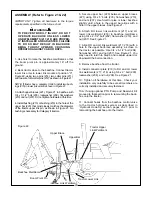
13. Tighten all hardware at this time. Check your
installation very carefully to be sure all members are
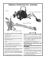
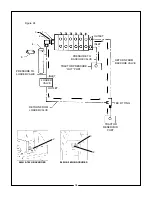
Figure 16
Backhoe Mainframe
Upper Brace
Upper Bar
Tractor Upper
Link Bracket
Link Weldment
Tractor Lower Link
C
correctly installed and securely fastened.
14. If using optional PTO Pump and Reservoir Kit
proceed to that section prior to remounting the back-
hoe onto the tractor.
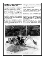
15. Connect hoses from the backhoe control valve to
the tractor hydraulic system as described in
“Hydraulic Hook-Up” section, prior to remounting the
backhoe onto the tractor.
16. Attach bumper plate (37) to backhoe mainframe
using two bolts (38), lockwashers, and flat washers
(35, 5) once the “Hydraulic Hook-Up” has been com-
pleted. See Figure 15.
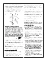
Hydraulic Hook-Up
If the optional Pump and Reservoir Kit is to be used,
refer to the instructions for that kit for proper assembly.
There are four basic methods of hooking up the back-
hoe to the hydraulic system of a tractor. The correct
method for the particular tractor will depend on the
remote couplers available, whether a loader valve or
other accessory valve is connected to the tractor sys-
tem, and whether the tractor has an open-center sys-
tem (constant pumping of oil to control valve and back
to reservoir) or a closed-center system (no flow of oil
until there is a demand at one hydraulic cylinder). The
four hook up methods are described below.
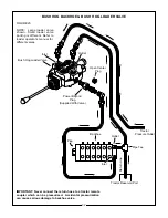
IMPORTANT: Follow instructions carefully when con-
necting backhoe to tractor hydraulic system.
The decal shown below is located on the Left Hand
toe shield.
25

